
Electric-component mounting system

a technology of mounting system and electric components, which is applied in the direction of machine supports, manufacturing tools, curtain suspension devices, etc., can solve the problems of affecting and affecting the operation of the system. , to achieve the effect of reducing the magnitude of reducing the total amount of system vibration generated within the cycle time, and improving the overall vibration of the system

Active Publication Date: 2006-05-16
FUJI MASCH MFG CO LTD
View PDF14 Cites 22 Cited by
  • Summary
  • Abstract
  • Description
  • Claims
  • Application Information

AI Technical Summary

Benefits of technology

[0018]In the electric-component mounting system according to the above mode (1) of this invention, the acceleration and deceleration values of each non-cycle-time determinant working device are suitably lowered so as to reduce the magnitude of the overall vibration of the electric-component mounting system. Even if it is not necessary to lower the acceleration and deceleration values of a given working device in relation to the kind of the electronic component or components, it is desirable to lower the acceleration and deceleration values of that working device, if possible, in relation to the required operating time of the other working device, since the lowering of the acceleration and deceleration values of the working device in question makes it possible to reduce the magnitude of the overall vibration of the system.
[0081]The magnitude of the overall vibration of the electric-component mounting system can be generally reduced by delaying the moment of initiation of the presently required operation of at least one non-cycle-time-determinant working device. Like the slowdown means, the operation-delaying means is effective also to reduce the operating noise and equalize the required amount of consumption of electric energy throughout the cycle time.

Problems solved by technology

Where the electric component held by suction by a suction nozzle under a negative pressure is moved or rotated about its axis, the electric component may be displaced or dislocated relative to the suction nozzle due to an inertia mass of the electric component, and may even fall from the suction nozzle in some condition, if the suction nozzle is moved or rotated at excessively high acceleration and deceleration values.
Similarly, the electric components already mounted on a circuit substrate may be displaced or dislocated relative to the circuit substrate or turned over on the circuit substrate, due to the inertia asses of the electric components, if the circuit substrate is moved at excessively high acceleration and deceleration values.
In addition, when the speed of abutting contact of the suction nozzle with the electric component when the suction nozzle holds the electric component by suction is excessively high, the electric component may be broken or damaged by the suction nozzle.

Method used


Image

  • Electric-component mounting system
  • Electric-component mounting system
  • Electric-component mounting system

Examples


second embodiment

[0229]While the sixteen mounting heads 130 are turned about the vertical common axis by the head-turning device 194 in the embodiment described above, the principle of the present invention is applicable to an electric-component mounting system which uses a mounting head that is arranged to be movable in the X-axis and Y-axis directions by an XY positioning device in an XY plane parallel to the plane of a printed-wiring board. An example of this type of electric-component mounting system will be described as this invention, by reference to FIGS. 17–24. This mounting system is constructed as disclosed in Japanese Patent No. 2824378.

[0230]Referring to FIG. 17, the electronic-component mounting system according to the second embodiment is shown generally at 601. The electronic-component mounting system 601 has a main body in the form of a machine base 600. The present mounting system 601 includes a printed-wiring board conveyor (PWB conveyor) 604, a component-mounting device 608 and co...

first embodiment

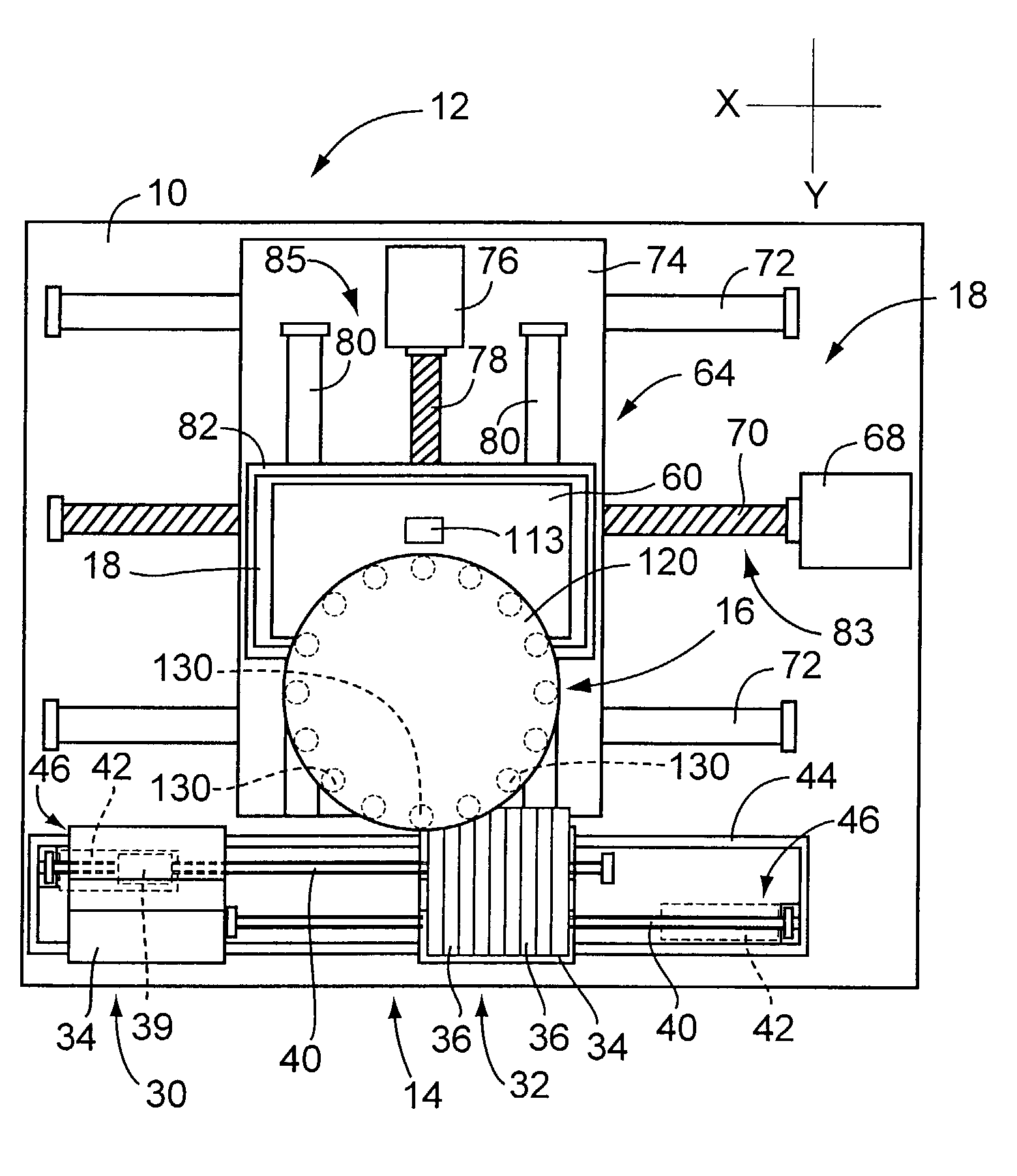
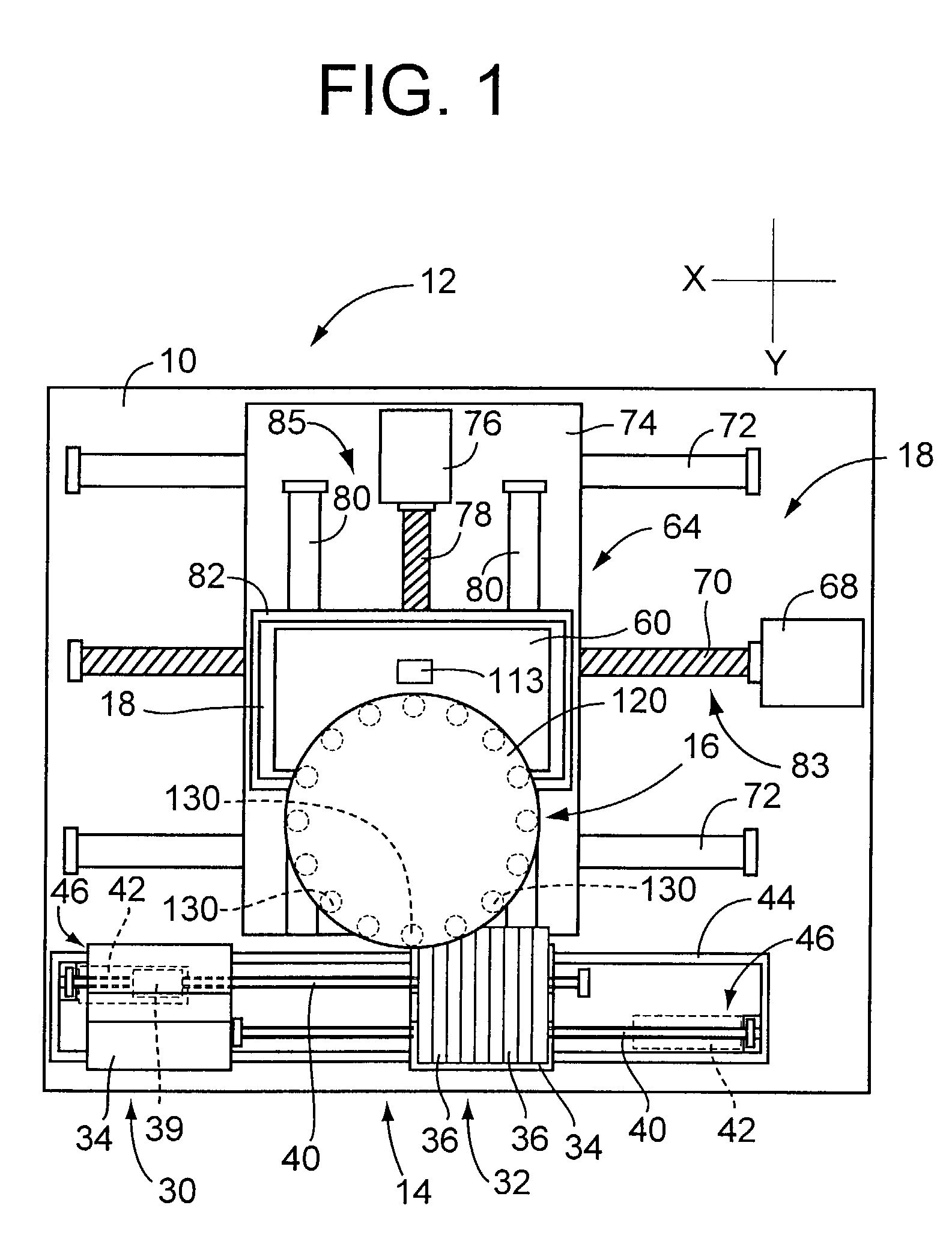
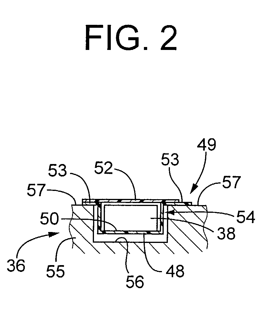
[0235]The component-supplying device 610 of tape feeder type has a component supply table 664, which includes a feeder carriage 662 and a multiplicity of tape feeders 660 that are mounted on the feeder carriage 622 such that the component-supply portions of the tape feeders 660 are arranged along a straight line parallel to the X-axis direction. Like the tape feeder 36 used in the first embodiment, each of the tape feeders 660 uses a carrier tape accommodating a succession of electronic components 606.

[0236]The component-supplying device 612 of tray type includes a multiplicity of component trays 666 as shown in FIG. 17. The component trays 666, which accommodate the electronic components 606, are accommodated in respective multiple tray boxes 668, which are vertically arranged and are supported by respective support members. The tray boxes 668 are elevated one after another by an elevator device disposed within a column 670, to a predetermined component-supply position. For a mount...


PUM

PropertyMeasurementUnit
Timeaaaaaaaaaa
Speedaaaaaaaaaa
Accelerationaaaaaaaaaa

Abstract

An electric-component mounting system wherein a determining device is operated for presently required operations of working devices disposed on a common main body, to determine a cycle-time-determinant working device which determines a cycle time of the system such that the cycle time is determined by a required operating time of the cycle-time-determinant working device as calculated when the presently required operation is performed at predetermined maximum acceleration and deceleration values or a predetermined maximum operating speed, and a slowdown device determines actual acceleration and deceleration values or an actual operating speed of each of non-cycle-time-determinant working device, so as to be lower than the predetermined maximum acceleration and deceleration values or operating speed thereof, such that the presently required operation of each non-cycle-time-determinant working device can be completed within the cycle time determined by the cycle-time-determinant working device.

Description

[0001]The present application is based on Japanese Patent Application No. 2001-143553 filed May 14, 2001, the content of which is incorporated herein by reference.BACKGROUND OF THE INVENTION[0002]1. Field of the Invention[0003]The present invention relates to an electric-component mounting system arranged to mount electric components (typically, electronic components), and more particularly to techniques for reducing vibrations in the system.[0004]2. Discussion of Related Art[0005]JP-A-11-11446 discloses an example of an electric-component mounting system wherein various working devices necessary to mount electric components on a circuit substrate are disposed on a common main body of the system. In the electric-component mounting system disclosed in the above-identified publication, the working devices disposed on the common main body of the system include: a component-supplying device operable to supply electric components; a printed-wiring-board holding device operable to hold th...

Claims


Application Information

Patent Timeline
IPC IPC(8): B23P19/00H05K13/04
CPCH05K13/0413H05K13/0452Y10T29/53183Y10T29/53187Y10T29/53178Y10T29/49128Y10T29/4913Y10T29/53261H05K13/041H05K13/0406
Inventor SUHARA, SHINSUKEITO, TOSHIYA
Owner FUJI MASCH MFG CO LTD
Learn More