Methods and systems for tracking a torsional orientation and position of an eye

a technology of torsional orientation and positioning, applied in the field of laser eye surgery methods and systems, can solve the problems of non-immunity of measurement system to measurement error, poor actual visual accuities provided by real-world wavefront correction system, and inability to deliver customized ablation patterns to the patient's eye, etc., to achieve the effect of improving laser eye surgery

Inactive Publication Date: 2006-05-16
AMO MFG USA INC
View PDF46 Cites 221 Cited by
  • Summary
  • Abstract
  • Description
  • Claims
  • Application Information

AI Technical Summary

Benefits of technology

[0010]In one aspect, the methods and software of the present invention can register a first image of the patient's eye with a second image of the patient's eye. In some embodiments, the methods can determine a torsional offset θ0 between the eye in the first image and the eye in the second image.
[0014]In another aspect, the present invention can track the torsional movement of the eye over time θ(t). Tracking of the torsional orientation of the patient's eye allows a computer processor to adjust a delivery of the customized ablation treatment to account for the changes in the position and orientation of the patient's eye.
[0015]In one particular configuration, the present invention provides for torsional tracking of the eye. A tracking algorithm can establish the exact amount of rotation of the eye with respect to the wavefront image taken during the wavefront measurement. This torsional rotation of the eye can be compensated for by making corresponding adjustment of the laser beam delivery.
[0017]In another aspect, the present invention provides a method of performing laser eye surgery. The method comprises measuring a wavefront measurement of the patient's eye. An image of the patient's eye is obtained during the measuring of the wavefront measurement. A laser treatment of the patient's eye is generated based on the wavefront measurement. The position of the patient's eye is registered with the image of the patient's eye obtained during the measuring of the wavefront measurement so that the customized laser treatment can accurately delivered to the patient's eye. The laser treatment is delivered to the patient's eye while the torsional orientation of the patient's eye is monitored. The delivery of the laser treatment is adjusted based on the monitored torsional orientation of the patient's eye.
[0019]In another embodiment, the present invention provides a laser surgery system comprising a system for registering a first image of an eye with a second image of an eye. Thee system includes a computer processor that is configured to receive a first image of an eye. An imaging device can be coupled to the computer processor. The imaging device can obtain a second image of the eye. The computer processor can be configured to locate a reference point, such as a pupil center, in the first and second image of the eye and locate at least one marker in the first image and find a corresponding marker in the second image. The computer processor can register the first and second image by substantially matching the reference points (e.g., pupil centers) and markers of the first and second image.

Problems solved by technology

Unfortunately, these measurement systems are not immune from measurement error.
Similarly, the calculation of the ablation profile, the transfer of information from the measurement system to the ablation system, and the operation of the ablation system all provide opportunities for the introduction of errors, so that the actual visual accuities provided by real-world wavefront-based correction systems may not be as good as might be theoretically possible.
One potential problem with the use of wavefront measurements is aligning the customized laser ablation pattern with the patient's eye.
However, when the laser eye surgery is being performed, the patient will generally be in a supine position, which may not position the patient's eye in the same position or torsional orientation as the eye when the wavefront measurement was taken.
Such torsional movement of the patient's eye during the ablation may cause a non-optimal delivery of the customized ablation pattern to the patient's eye, particularly in cases of astigmatism and other-non-rotationally symmetric aberrations.

Method used


Image

  • Methods and systems for tracking a torsional orientation and position of an eye
  • Methods and systems for tracking a torsional orientation and position of an eye
  • Methods and systems for tracking a torsional orientation and position of an eye

Examples


Embodiment Construction

[0062]The present invention is particularly useful for enhancing the accuracy and efficacy of laser eye surgical procedures such as photorefractive keratectomy (PRK), phototherapeutic keratectomy (PTK), laser in situ keratomileusis (LASIK), and the like. The efficacy of the laser eye surgical procedures can be enhanced by tracking the torsional orientation of the patient's eye so that a laser ablation pattern is more accurately aligned with the real-time orientation of the patient's eye.

[0063]While the system and methods of the present invention are described primarily in the context of improving a laser eye surgery system, it should be understood the techniques of the present invention may be adapted for use in alternative eye treatment procedures and systems such as femtosecond lasers and laser treatment, infrared lasers and laser treatments, radial keratotomy (RK), scleral bands, follow up diagnostic procedures, and the like.

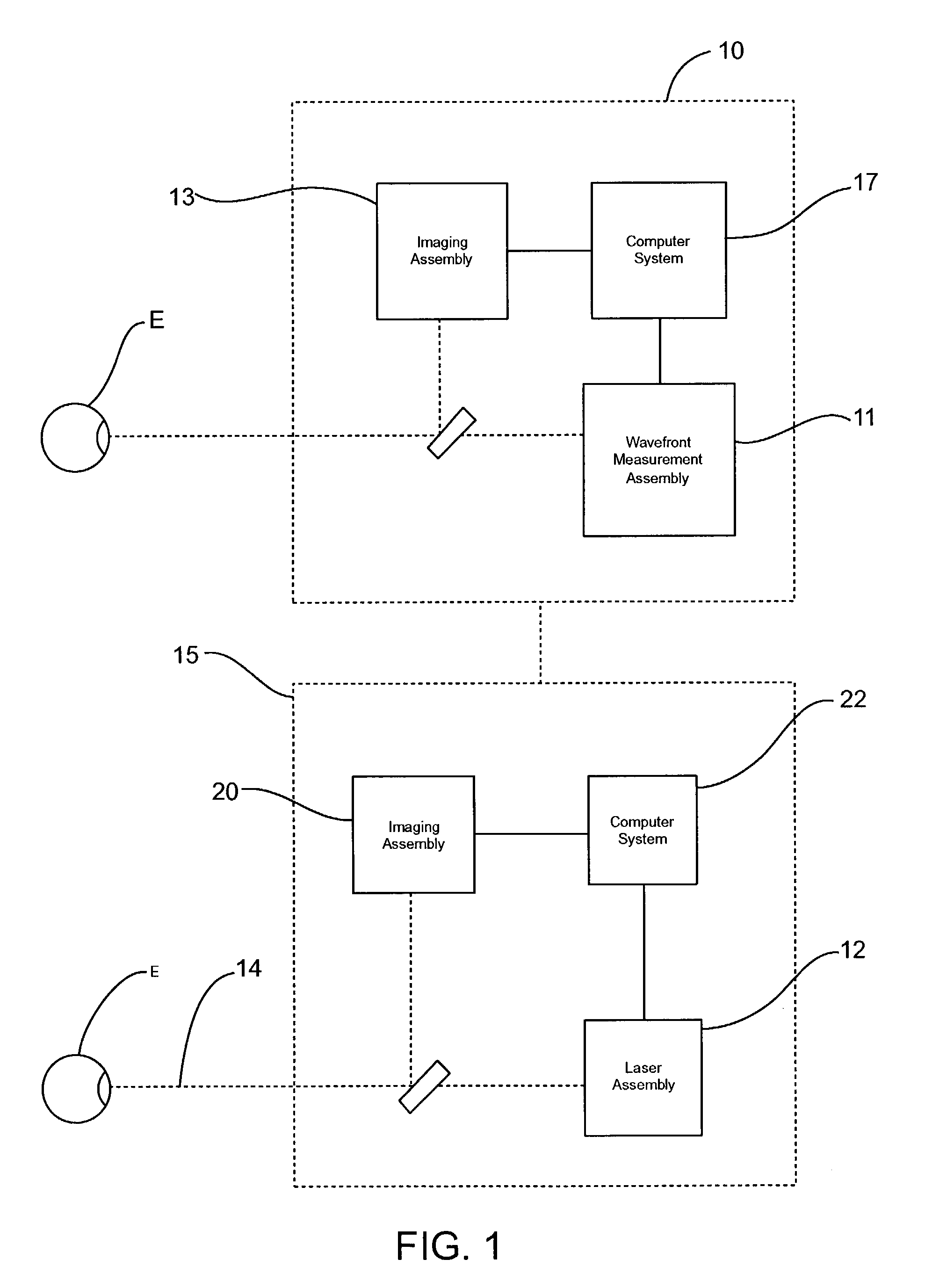
[0064]FIG. 1 schematically illustrates a simplified sys...


PUM


Abstract

Methods and systems for tracking a position and torsional orientation of a patient's eye. In one embodiment, the present invention provides methods and software for registering a first image of an eye with a second image of an eye. In another embodiment, the present invention provides methods and software for tracking a torsional movement of the eye. In a particular usage, the present invention tracks the torsional cyclorotation and translational movement of a patient's eye so as to improve the delivery of a laser energy to the patient's cornea.

Description

CROSS-REFERENCE TO RELATED APPLICATIONS[0001]The present application claims benefit to U.S. Provisional Patent Application No. 60 / 384,653, filed May 30, 2002, the complete disclosure of which is incorporated herein by reference.BACKGROUND OF THE INVENTION[0002]The present invention relates generally to laser eye surgery methods and systems. More specifically, the present invention relates to registering a first image of a patient's eye with a second image of a patients eye and to tracking a position and a torsional orientation of the patient's eye during laser eye surgery so as to register a customized ablation profile with the patient's eye.[0003]Known laser eye procedures generally employ an ultraviolet or infrared laser to remove a microscopic layer of stromal tissue from the cornea of the eye to alter the refractive characteristics of the eye. The laser removes a selected shape of the corneal tissue, often to correct refractive errors of the eye. Ultraviolet laser ablation resul...

Claims


Application Information

Patent Timeline
Patent Type & Authority Patents(United States)
IPC IPC(8): A61B3/14A61B18/18G06K9/32A61B3/113G01B11/00A61F9/007A61F9/008A61F9/01G01B11/26G06T1/00G06T3/00
CPCA61B3/1015A61F9/00806A61F9/00829G06T7/003A61B3/00G06F3/013A61B3/0025A61F9/00804A61B3/113A61F2009/00897A61F9/00825A61F2009/00844A61F2009/00846A61F2009/00848A61F2009/00872A61F2009/0088G06T2207/30041A61F2009/00882G06T7/337A61B3/14A61F9/008G06T7/0014
Inventor CHERNYAK, DIMITRI
Owner AMO MFG USA INC
Why Eureka
Try Eureka