Splint assembly for improving cardiac function in hearts, and method for implanting the splint assembly

a heart and splint technology, applied in the direction of staples, nails, medical devices, etc., can solve the problems of heart failure, significant increase in wall tension and/or stress, and dilatation of the left ventricular chamber, so as to reduce the energy consumption of the failing heart, and reduce the isovolumetric contraction

Inactive Publication Date: 2006-05-16
EDWARDS LIFESCIENCES LLC
View PDF259 Cites 135 Cited by
  • Summary
  • Abstract
  • Description
  • Claims
  • Application Information

AI Technical Summary

Benefits of technology

[0015]One aspect of the present invention pertains to a non-pharmacological, passive apparatus and method for the treatment of a failing heart due to dilatation. The device is configured to reduce the tension in the heart wall, and thereby reverse, stop or slow the disease process of a failing heart as it reduces the energy consumption of the failing heart, decreases isovolumetric contraction, increases isotonic contraction (sarcomere shortening), which in turn increases stroke volume.
[0016]The device reduces wall tension by changing chamber geometry or shape and / or changing the radius of curvature or cross-section of a heart chamber. These changes may occur during the entire cardiac cycle. The apparatuses of the present invention which reduce heart wall stress in this way can be referred to generally as “splints.” Splints can be grouped as either “full cycle splints,” which engage the heart to produce these changes throughout the cardiac cycle, or “restrictive splints,” which engage the heart wall for only a portion of the cardiac cycle to produce these changes.

Problems solved by technology

Typically these processes result in dilatation of the left ventricular chamber.
With damage to the myocardium or chronic volume overload, however, there are increased requirements put on the contracting myocardium to such a level that this compensated state is never achieved and the heart continues to dilate.
The basic problem with a large dilated left ventricle is that there is a significant increase in wall tension and / or stress both during diastolic filling and during systolic contraction.
However, in a failing heart, the ongoing dilatation is greater than the hypertrophy and the result is a rising wall tension requirement for systolic contraction.
This is felt to be an ongoing insult to the muscle myocyte resulting in further muscle damage.
Additionally, because of the lack of cardiac output, a rise in ventricular filling pressure generally results from several physiologic mechanisms.
These drug therapies offer some beneficial effects but do not stop the progression of the disease.
Heart transplantation has serious limitations including restricted availability of organs and adverse effects of immunosuppressive therapies required following heart transplantation.
However, this extremely invasive procedure reduces muscle mass of the heart.
Finally, mitral regurgitation is a condition whereby blood leaks through the mitral valve due to an improper positioning of the valve structures that causes it not to close entirely.
If the infarcted or aneurysmal region is located in the vicinity of the mitral valve, geometric abnormalities may cause the mitral valve to alter its normal position and dimension, and may lead to annular dilatation and the development of mitral regurgitation.

Method used


Image

  • Splint assembly for improving cardiac function in hearts, and method for implanting the splint assembly
  • Splint assembly for improving cardiac function in hearts, and method for implanting the splint assembly
  • Splint assembly for improving cardiac function in hearts, and method for implanting the splint assembly

Examples


Embodiment Construction

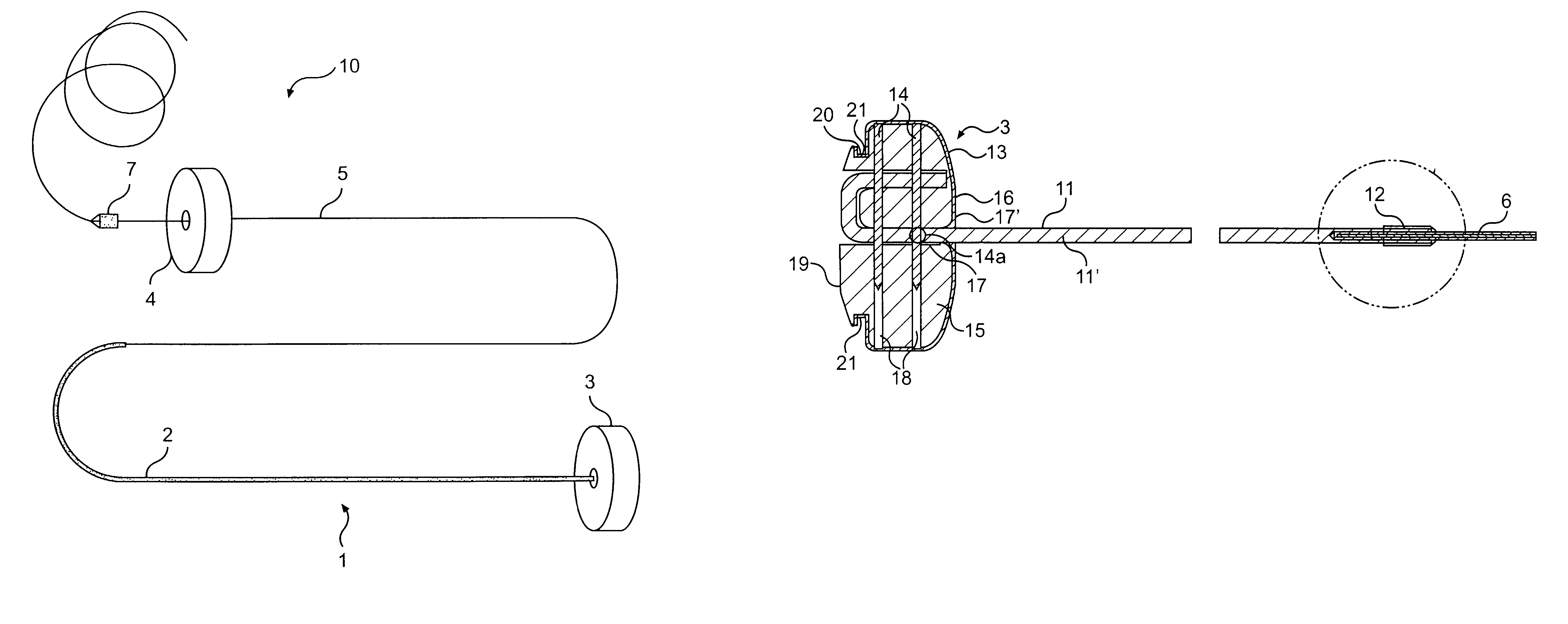
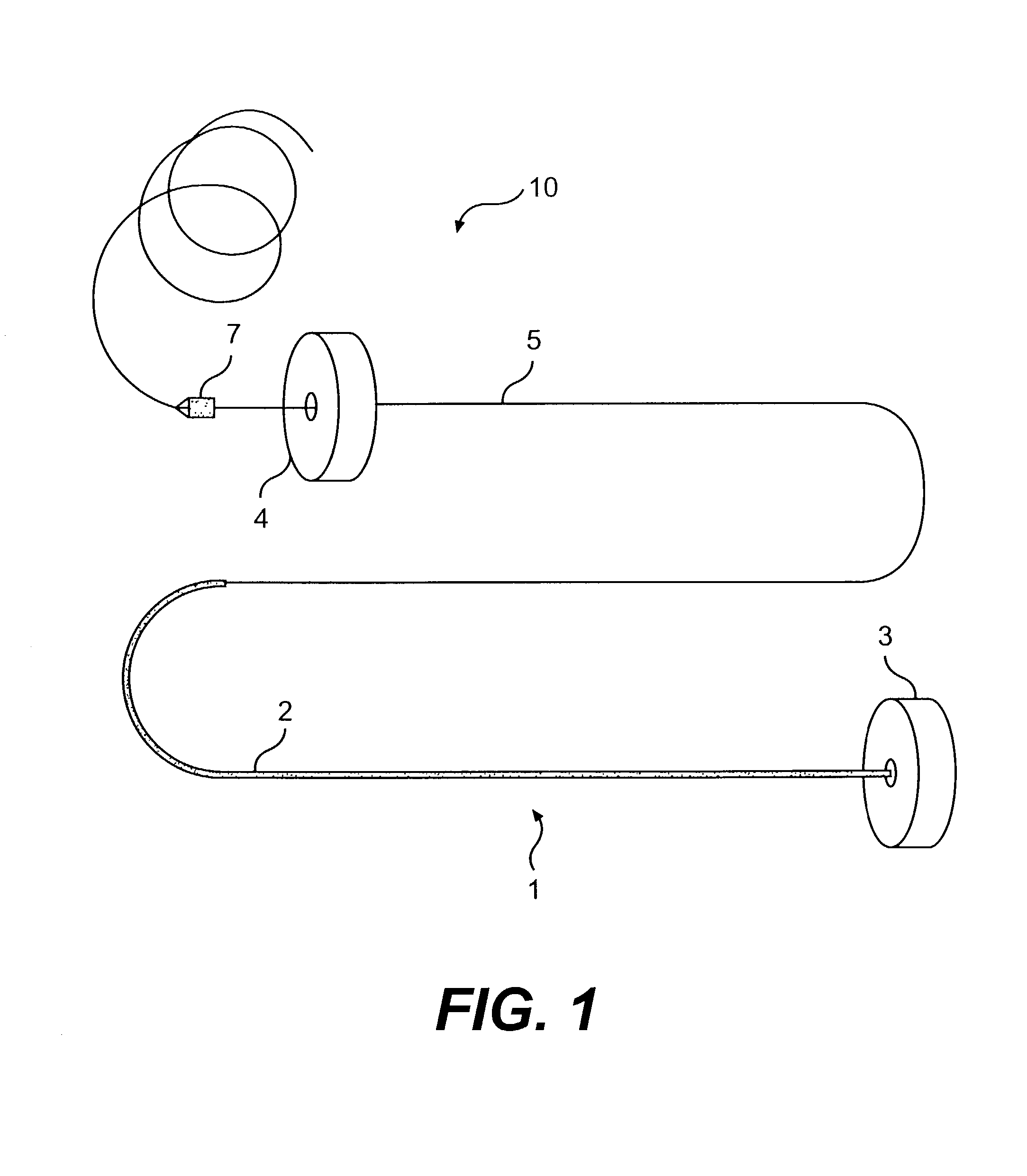
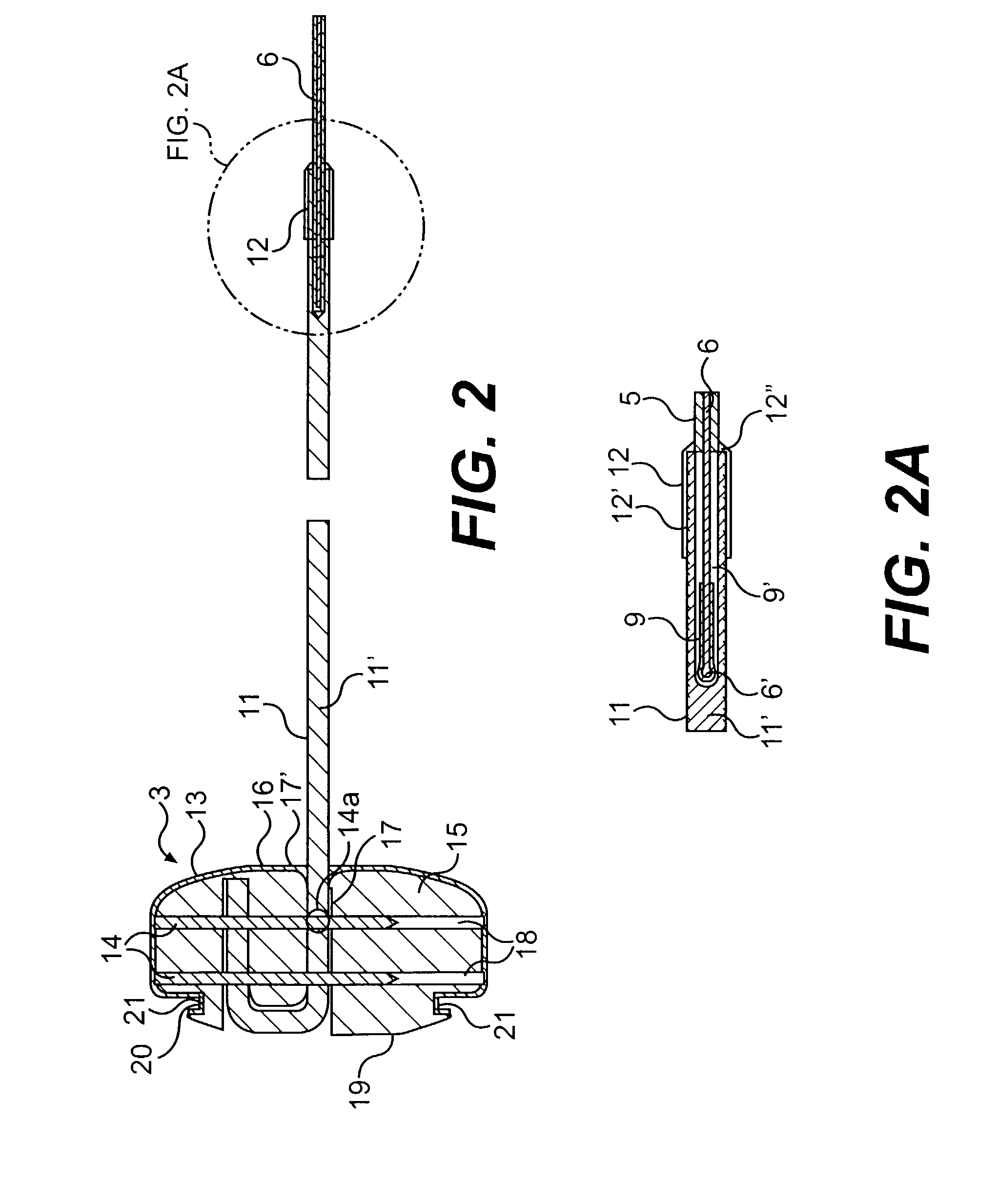
[0042]The various aspects of the invention to be discussed herein generally pertain to devices and methods for treating heart conditions, including, for example, dilatation and other similar heart failure conditions. The device of the present invention preferably operates passively in that, once placed in the heart, it does not require an active stimulus, either mechanical, electrical, or otherwise, to function. Implanting one or more of these devices alters the shape or geometry of the heart, both locally and globally, and thereby increases the heart's efficiency. That is, the heart experiences an increased pumping efficiency through an alteration in its shape or geometry and concomitant reduction in stress on the heart walls.

[0043]Although the implanted device for treating the heart preferably is a passive device, it is contemplated that the inventive tools and instruments used for implanting the device and the method of using these tools and instruments can be used to implant oth...


PUM


Abstract

A splint assembly for placement transverse a heart chamber to reduce the heart chamber radius and improve cardiac function has a tension member formed of a braided cable with a covering. A fixed anchor assembly is attached to one end of the tension member and a leader for penetrating a heart wall and guiding the tension member through the heart is attached to the other end. An adjustable anchor assembly can be secured onto the tension member opposite to the side on which the fixed pad assembly is attached. The adjustable anchor assembly can be positioned along the tension member so as to adjust the length of the tension member extending between the fixed and adjustable anchor assemblies. The pad assemblies engage with the outside of the heart wall to hold the tension member in place transverse the heart chamber. A probe and marker delivery device is used to identify locations on the heart wall to place the splint assembly such that it will not interfere with internal heart structures. The device delivers a marker to these locations on the heart wall for both visual and tactile identification during implantation of the splint assembly in the heart.

Description

[0001]This application is a continuation of U.S. application Ser. No. 09 / 532,049, filed Mar. 21, 2000, now U.S. Pat. No. 6,537,198, which is incorporated herein by reference.FIELD OF THE INVENTION[0002]The present invention pertains to a device, and a method for placing the device, for treating a failing heart. In particular, the device and its related method of the present invention are directed toward reducing the wall stress in a failing heart. The device reduces the radius of curvature and / or alters the geometry or shape of the heart to thereby reduce wall stress in the heart and improve the heart's pumping performance.BACKGROUND OF THE INVENTION[0003]Heart failure is a common course for the progression of many forms of heart disease. Heart failure may be considered as the condition in which an abnormality of cardiac function is responsible for the inability of the heart to pump blood at a rate commensurate with the requirements of the metabolizing tissues, or can do so only at ...

Claims


Application Information

Patent Timeline
Patent Type & Authority Patents(United States)
IPC IPC(8): A61M31/00A61B17/12A61B17/00A61B17/04A61B17/064A61B17/068A61B19/00
CPCA61B17/00234A61B17/0401A61F2/2487A61B17/064A61B17/0682A61B19/54A61B2017/00243A61B2017/0412A61B2017/0437A61B2017/0464A61B2017/048A61B2017/0496A61B2017/0404A61B90/39
Inventor VIDLUND, ROBERTPAULSON, THOMASMORTIER, TODDSCHWEICH, JR., CYRILLAPLANTE, JEFFREYKUSZ, DAVIDSCHROEDER, RICHARD
Owner EDWARDS LIFESCIENCES LLC
Why Eureka
Try Eureka