Density detection using real time discrete photon counting for fast moving targets

a discrete photon and target technology, applied in liquid/fluent solid measurement, machines/engines, instruments, etc., can solve the problems of limiting the number of vehicles that can be inspected, taking a half hour or more, and inconvenient and time-consuming for both customs officials and the driver and occupant of the vehicl

Inactive Publication Date: 2006-05-16
LEIDOS
View PDF48 Cites 94 Cited by
  • Summary
  • Abstract
  • Description
  • Claims
  • Application Information

AI Technical Summary

Benefits of technology

[0025]Still further to this embodiment, the method comprises adjusting the data from the one or more side vertical rows and the center vertical row using the adjustment distance 1 for each of the multiple planes to form undistorted images for each of the multiple rows and comparing the undistorted images for each of the multiple planes to determine the location of an object within the target.

Problems solved by technology

Unfortunately, most common conventional inspection mechanisms require either visual inspection by others and / or scent inspection by dogs.
These conventional inspection methods require that the vehicle stop and wait for the inspection to be completed, which can take a half hour or more.
This is both inconvenient and time consuming for both customs officials and the vehicle drivers and occupants, and severely limits the number of vehicles that can be inspected each day.
Furthermore, such inspection may put officers at personal risk if a vehicle has been booby-trapped or if the vehicle's driver or other occupants become nervous and decide to attack the customs officer inspecting their vehicle.
Unfortunately, this approach in the prior art requires that the vehicle be stopped and evacuated prior to inspection, because such high levels of radiation can be physically harmful to the vehicle's occupants if they remain in the vehicle during inspection.
Disadvantageously, prior art inspection systems using high levels of radiation not only require that the vehicle be stopped, and therefore delayed, but pose a risk to stowaways that may be aboard the vehicle, and unwilling to voluntarily evacuate when the vehicle is stopped for inspection.
A further problem posed by manual inspection techniques arises when tanker trucks or railroad cars, after having been emptied, seek to cross a border in order to refill.
(The venting of noxious gasses would be hazardous and ecologically unacceptable.)
Thus, the contents of such tankers typically go uninspected by customs agents in order to avoid the time-consuming (up to 3 days, with nitrogen purging) venting of such gases.
Unfortunately, drug smugglers are well aware of this fact, and therefore utilize tanker trucks and railroad cars to import illegal drugs, knowing that they will not be inspected at the border.
Yet a further problem with prior vehicle inspection systems is that some, employing complex x-ray inspection sources, move a vehicle past a source and detector, which constitute heavy equipment subject to frequent breakdowns, and requiring very high capital costs for installation.
The X-ray source is expensive to buy and to install and requires an appreciable amount of power to operate, is sensitive to ambient humidity and motion-shock and is expensive and time- consuming to repair.
Furthermore, these expensive X-ray sources also require a permanent shielding structure, which, along with the vehicle-moving mechanism, boosts the capital costs to nearly $10,000,000 for one such system, limiting the numbers which can be in use at borders.

Method used


Image

  • Density detection using real time discrete photon counting for fast moving targets
  • Density detection using real time discrete photon counting for fast moving targets
  • Density detection using real time discrete photon counting for fast moving targets

Examples


Embodiment Construction

is a source code listing of a firmware operating system including steps traversed by each 16-channel processing unit of FIG. 4 in order to quickly relay the photon count information received from the detectors to the computer.

[0040]Corresponding reference characters indicate corresponding components throughout the several views of the drawings.

DETAILED DESCRIPTION OF THE PREFERRED EMBODIMENTS

[0041]The following description of the presently contemplated best mode of practicing the invention is not to be taken in a limiting sense, but is made merely for the purpose of describing the general principles of the invention. The scope of the invention should be determined with reference to the claims.

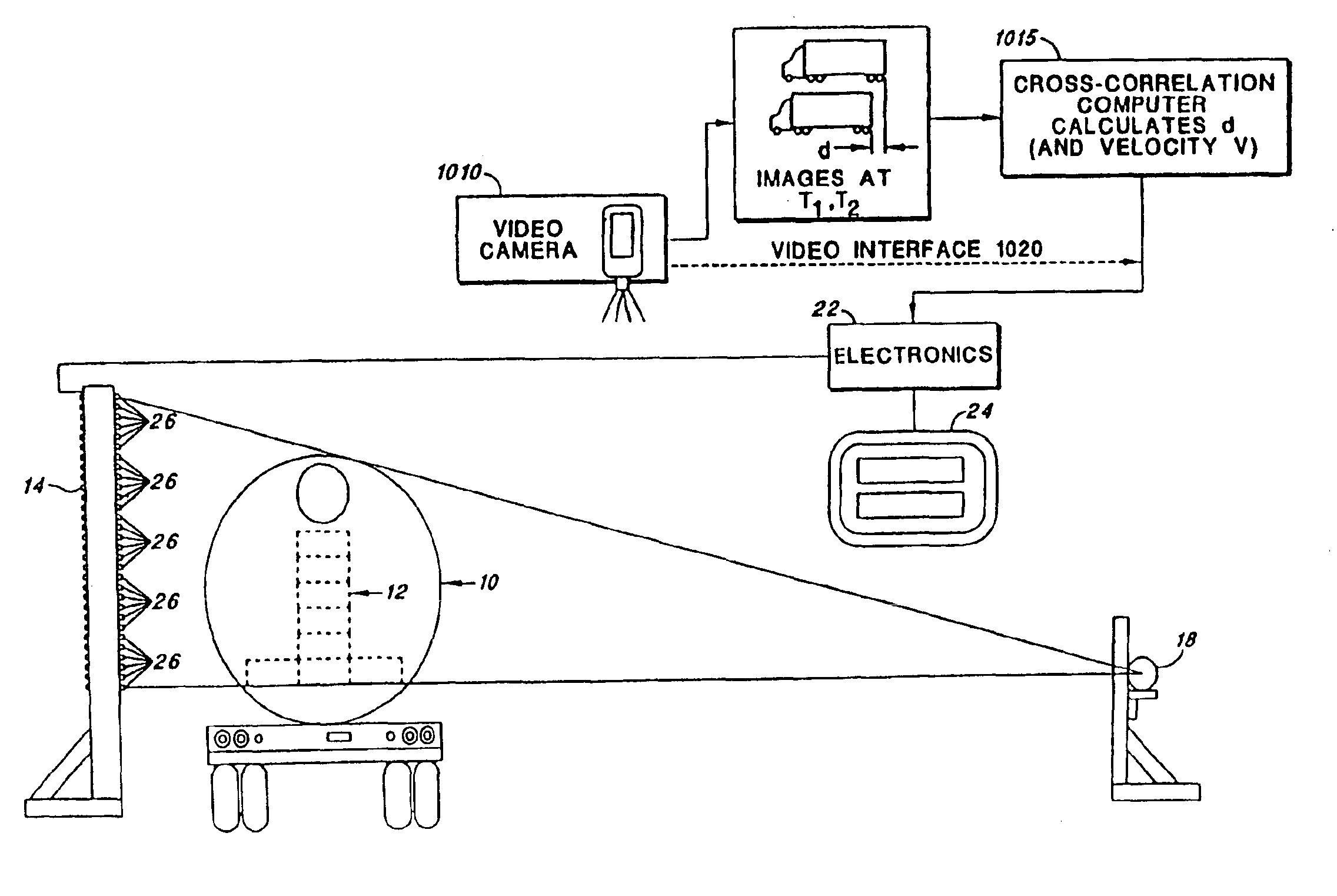
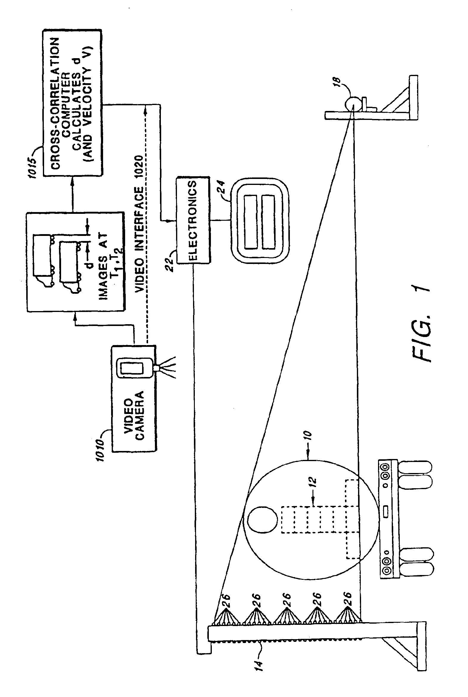
[0042]Referring first to FIG. 1, a schematic diagram is shown of a system made in accordance with one embodiment of the present invention and of a fast-moving target object 10 (“target object”, or “tanker truck”, “truck”, or “railroad car”) containing contraband, wherein discrete photon countin...


PUM

PropertyMeasurementUnit
speedsaaaaaaaaaa
diameteraaaaaaaaaa
gamma-ray energyaaaaaaaaaa

Abstract

A system for detecting and graphically displaying a contents of a fast-moving target object comprises: a radiation source, having a position such that at least a portion of radiation emitted from the radiation source passes through the fast-moving target object, the fast-moving target object having a variable velocity and acceleration while maintaining a substantially constant distance from the radiation source and being selected from the group consisting of: a vehicle, a cargo container and a railroad car; a velocity measuring device configured to measure the variable velocity of the fast-moving target object; a detector array comprising a plurality of photon detectors, having a position such that at least some of the at least a portion of the radiation passing through the target object is received thereby, the detector array having a variable count time according to the variable velocity and a grid unit size; a counter circuit coupled to the detector array for discretely counting a number of photons entering individual photon detectors, the counter circuit measuring a count rate according to a contents within the fast-moving target object; a high baud-rate interface coupled to the counter circuit for sending count information from the counter circuit at a rate fast enough to support real-time data transfer therethrough; and a processor coupled to the velocity measuring device and to the high-baud-rate interface, receiving count information from the high baud-rate interface and generating distortion-free image data in real time as a function of the count information and the variable velocity. A method for using the system is also disclosed.

Description

[0001]This is a Continuation-in-Part Application of U.S. Ser. No. 09 / 398,547, for DENSITY DETECTION USING REAL TIME DISCRETE PHOTON COUNTING FOR FAST MOVING TARGETS, filed Sep. 17, 1999 now U.S. Pat. No. 6,507,025, by Verbinski, et al., which is a Continuation-in-Part Application of U.S. Ser. No. 08 / 921,854 of Verbinski et al., for DENSITY DETECTION USING DISCRETE PHOTON COUNTING, filed Sep. 2, 1997 now abandoned, which is a Continuation Application of U.S. Ser. No. 08 / 546,999 of Verbinski et al., for DENSITY DETECTION USING DISCRETE PHOTON COUNTING filed Oct. 23, 1995, now abandoned, both of which are incorporated herein by reference.[0002]A portion of the disclosure of this patent document contains material that is subject to copyright protection. The copyright owner has no objection to the facsimile reproduction by anyone of this patent document or the patent disclosure, as it appears in the United States Patent and Trademark Office patent files or records, but otherwise reserves...

Claims


Application Information

Patent Timeline
Patent Type & Authority Patents(United States)
IPC IPC(8): G01N23/10G01T1/20G01N23/02G01V5/00
CPCG01N23/02G01V5/0066G01V5/0016
Inventor VERBINSKI, VICTORSMITH, SCOTTMAXWELL, JUDITHADAMS, JEFFREYSHYFFER, RYANVALENTINE, KENNETH
Owner LEIDOS
Why Eureka
Try Eureka