Gas discharge panel with electrodes comprising protrusions, gas discharge device, and related methods of manufacture

a technology of gas discharge panel and electrode, which is applied in the manufacture of electrode systems, cold cathode, electric discharge tube/lamps, etc., can solve the problems of reducing yield rates, very involved in manufacturing processes, and inability to manufacture crts with diagonal screen sizes exceeding 40 inches, etc., to achieve excellent discharge capacity, improve illuminance efficiency, and excellent discharge capacity

Inactive Publication Date: 2006-05-16
PANASONIC CORP
View PDF34 Cites 24 Cited by
  • Summary
  • Abstract
  • Description
  • Claims
  • Application Information

AI Technical Summary

Benefits of technology

[0012]According to the above construction, a shortest gap (discharge gap) between each pair of display electrodes is either the gap between one of the bus lines and the inner protrusions provided on the opposite bus line or the gap between the inner protrusions provided on both of the bus lines. Discharge is generated in the shortest gap. By concentrating the electric charge within the shortest gap during the discharge period, it is possible to keep the discharge firing voltage below existing levels. Also, the generated discharge gradually expands to the outer protrusions, allowing a sustain discharge (surface discharge) to be secured over a wide area. Thus the present inventi

Problems solved by technology

CRTs are widely used in televisions and the like for their high resolution and image quality, although the large increases in device depth and weight that accompany increases in screen size mean that CRTs having a diagonal screen size exceeding 40 inches are not considered feasible.
LCDs by far exceed CRTs in terms of reduced energy consumption, device depth, and weight, and are now widely used as computer monitors, although the intricate construction of thin film transistors (TFT), the most common type of LCD, means that the manufacturing process is very involved.
Increases in screen size consequently lead to a dr

Method used


Image

  • Gas discharge panel with electrodes comprising protrusions, gas discharge device, and related methods of manufacture
  • Gas discharge panel with electrodes comprising protrusions, gas discharge device, and related methods of manufacture
  • Gas discharge panel with electrodes comprising protrusions, gas discharge device, and related methods of manufacture

Examples


first embodiment

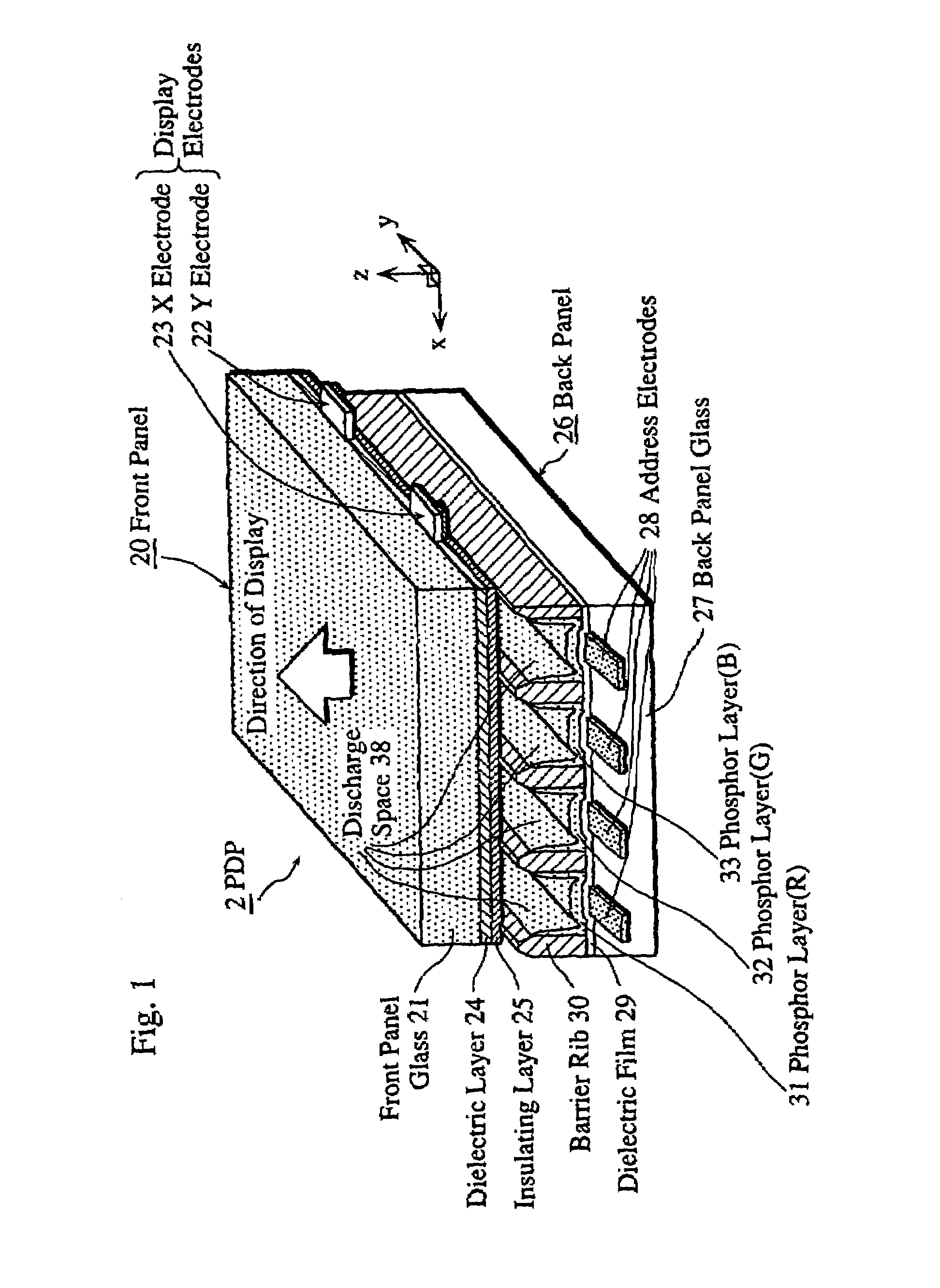
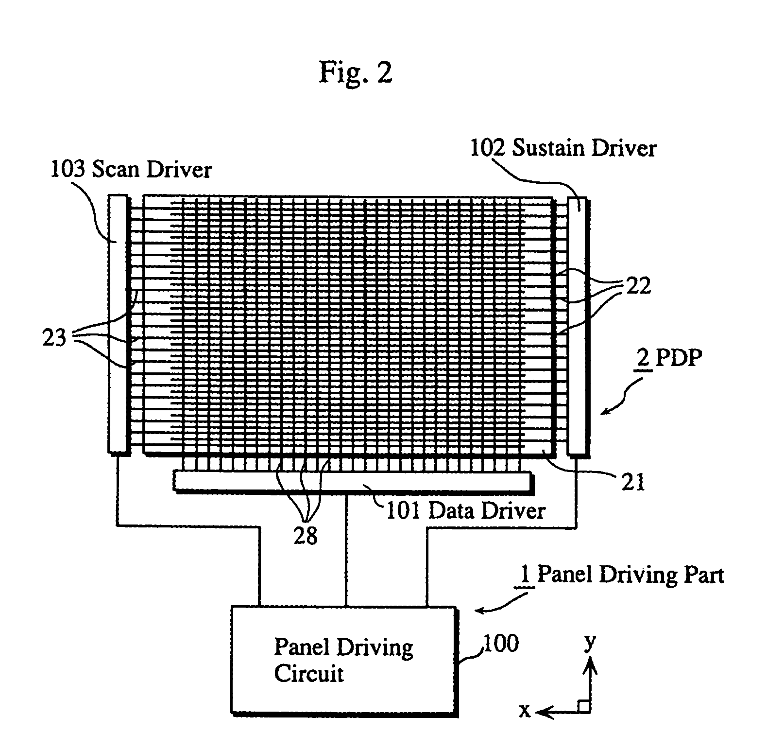
[0054]FIG. 1 is a cross-sectional perspective view showing a principal construction of an AC PDP module (hereafter “PDP 2”) of a PDP display apparatus, being an example gas discharge apparatus of the first embodiment. In FIG. 1, the PDP 2 is thick in a z direction and the surface of the PDP 2 runs parallel to the xy plane. This description applies to all the figures discussed below. The PDP display apparatus of the first embodiment is divided broadly into the PDP 2 and the panel driving part 1 described below. The construction of a panel driving part 1 is the same with respect to the first, second, and third embodiments, and to each of the variations 1-1˜1-12 and 2-1˜2-13.

[0055]As shown in FIG. 1, the PDP 2 is formed by a front panel 20 and a back panel 26 arranged so as to face each other. A front panel glass 21 forming the substrate of the front panel 20 is arranged on one side with plural pairs of display electrodes 22 and 23 (Y electrode 22, X electrode 23) running parallel in t...

second embodiment

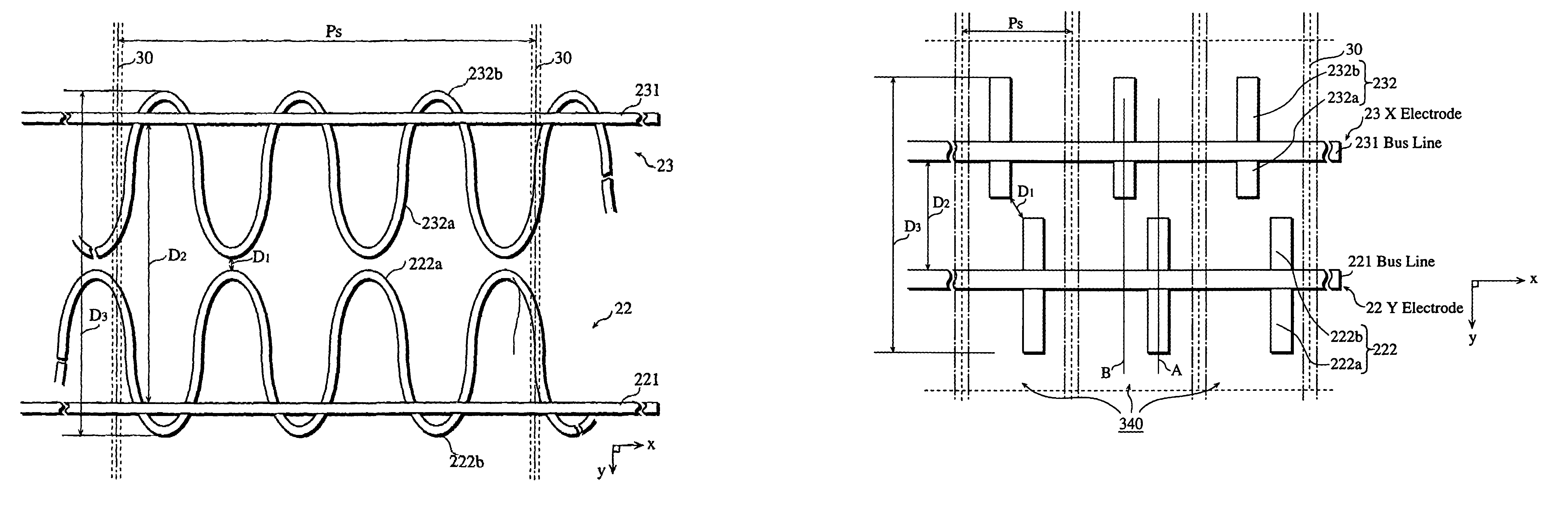
[0093]FIG. 12 is a frontal illustration of the display electrodes of the PDP 2 of the second embodiment. FIG. 12 shows a construction having only one isolated electrode arranged on each of the bus lines 221 and 231 within each cell 340. It is, however, possible to arrange two isolated electrodes per cell, as in the first embodiment, in which case it is desirable to arrange the isolated electrodes 222 and 232 to satisfy the relation Pe=A×Ps / n.

[0094]In the second embodiment, the isolated electrodes 222 and 232 are arranged, as in the first embodiment, according to Paschen's Law, this time to have a gap (shortest gap D1) of 40 μm therebetween. As shown in FIG. 13, the squared ends of each of the inner protrusions 222a and 232a are out of alignment in the x direction. The inner protrusions 222a and 232a can be arranged, as in FIG. 12, so that central lines A and B running in the y direction are out of alignment. The “central lines” referred to here are the lines dividing the surface of ...

third embodiment

[0109]The construction of the display electrodes 22 and 23 of the third embodiment is the same as that of the first embodiment (see FIG. 4). The characteristics of the third embodiment relate mainly to the construction of the insulating layer 25. FIG. 22 is a cross-sectional view of a section of the thickness (in the z direction) of the PDP 2 of the third embodiment.

[0110]According to the construction of the PDP 2 shown in FIG. 22, an insulating layer 251 of magnesium oxide (MgO) is formed over an area corresponding to the inner protrusions 222a and 232a (i.e. the area directly above the inner protrusions 222a and 232a in FIG. 22), and an insulating layer 252 of aluminum oxide (Al2O3) is formed over the remaining area, both insulating layers 252 and 253 being formed so as to cover over the dielectric layer 24 which covers the entire surface of the front panel glass 21. The use of both magnesium oxide and aluminum oxide in the third embodiment results in the rate of electron discharg...


PUM


Abstract

A gas discharge panel to increase the illuminance efficiency and a method of manufacturing includes providing a plurality of cells arranged in a matrix between a pair of substrates. Pairs of display electrodes are arranged on an inner surface of one of the substrates and include two bus lines lying parallel to each other with one or more inner protrusions arranged within each cell relative to the bus lines. This arrangement provides a relatively short discharge gap between the pair of display electrodes.

Description

TECHNICAL FIELD[0001]The present invention relates generally to a gas discharge panel and a gas display device used for TV displays and the like, and more particularly to a plasma display panel (PDP).BACKGROUND ART[0002]The demand in recent years for wide-screen displays with an image quality typified by high-vision has seen much research directed into cathode ray tube (CRT), liquid crystal display (LCD), and plasma display panel (PDP) technologies. CRTs are widely used in televisions and the like for their high resolution and image quality, although the large increases in device depth and weight that accompany increases in screen size mean that CRTs having a diagonal screen size exceeding 40 inches are not considered feasible.[0003]LCDs by far exceed CRTs in terms of reduced energy consumption, device depth, and weight, and are now widely used as computer monitors, although the intricate construction of thin film transistors (TFT), the most common type of LCD, means that the manufa...

Claims


Application Information

Patent Timeline
IPC IPC(8): H01J17/49H01J11/24H01J9/02H01J11/40
CPCH01J11/12H01J11/28H01J11/24H01J2211/245H01J11/40H01J9/02
Inventor MURAI, RYUICHITAKADA, YUUSUKESHIOKAWA, AKIRATANAKA, HIROYOSI
Owner PANASONIC CORP
Why Eureka
Try Eureka