Oscillator circuit, oscillator circuit adjusting method, and mass measuring apparatus using oscillator circuit

a technology of oscillator circuit and oscillator circuit, which is applied in the direction of oscillator generator, pulse automatic control, weighing by absorbing components, etc., can solve the problems of quartz vibrator in liquid to oscillate, quartz vibrator in air to oscillate, and difficult oscillation of quartz vibrator, etc., to ensure the oscillation of piezoelectric vibrator, stable oscillation, and high reliability

Inactive Publication Date: 2006-05-16
SEIKO EPSON CORP
View PDF7 Cites 14 Cited by
  • Summary
  • Abstract
  • Description
  • Claims
  • Application Information

AI Technical Summary

Benefits of technology

[0013]where A represents the gain of the amplifying circuit and β represents the feedback ratio of the feedback circuit. Here, Re(Aβ) and Im(Aβ) represent the real part and the imaginary part, respectively, of a complex quantity Aβ. As described above, in order to cause the oscillator circuit to oscillate, the amplification, which is a power condition, must be 1 or more and the phase of an oscillator loop must be 0 degrees. Thus, a phase-shift circuit is provided both in the amplifying circuit and the feedback circuit, so that the phase-shift circuit in the amplifying circuit can adjust the phase of the entire loop. Thus, a phase condition, which is one of the oscillation conditions, is satisfied so that an influence of the feedback circuit (feedback loop) on the gain is minimized.
[0015]As described above, in order to satisfy the phase condition for oscillation and the gain condition of the oscillator loop both in gas, such as air, and liquid, the amount of phase shift of the entire oscillator loop is adjusted to an appropriate value by the first phase-shift circuit. Also, in order to obtain an oscillator loop gain and to achieve the phase condition for stable oscillation, the reactance of the second phase-shift circuit arranged in the feedback circuit is adjusted. Since the first phase-shift circuit is separated from the second phase-shift circuit in terms of impedance by the amplifiers having a buffer function due to impedance conversion, the phase of the entire closed loop can be adjusted irrespective of the gain characteristics of the feedback circuit. Thus, the phase condition and gain condition of the oscillator circuit are satisfied so that stable and easy oscillation of the piezoelectric vibrator both in air and liquid can be ensured.
[0016]The phase-shift circuit may include a tank circuit that resonates at an oscillation frequency of the vibrator. Thus, even if the amplification of the oscillator loop is increased, undesirable oscillation, such as parasitic oscillation, spurious oscillation, and feedback oscillation, can be avoided. In other words, an input frequency equal to the resonance frequency of the tank circuit rapidly increases the impedance when viewed from the closed loop side, and an input frequency deviated from the resonance frequency reduces the impedance. Thus, by setting the resonance frequency of the tank circuit to be substantially equal to the oscillation frequency of the piezoelectric vibrator, the amplification of the closed loop at frequencies other than the oscillation frequency of the piezoelectric vibrator is reduced. Therefore, undesirable oscillation, such as parasitic oscillation, spurious oscillation, and feedback oscillation, can be avoided.
[0017]At least one of the first phase-shift circuit and the second phase-shift circuit may include a voltage-controlled phase-shift circuit capable of adjusting the phase of the oscillator loop in accordance with a control voltage from the outside. The impedance characteristics of a piezoelectric vibrator in a liquid change depending on the state of the liquid, the wettability of the liquid to the piezoelectric vibrator, the contact condition of the liquid to the surface of the piezoelectric vibrator, and the like. By the phase-shift circuit formed by the voltage-controlled phase-shift circuit, the oscillator circuit can be precisely adjusted. Thus, a stable operation of the oscillator circuit in liquid can be achieved.
[0020]Preferably, in the gain adjusting step, a negative resistance is set to be three or more times larger than the impedance of the piezoelectric vibrator. Thus, oscillation of the piezoelectric vibrator can be ensured. Also, preferably, each of the steps for adjusting the oscillator circuit is performed when the oscillator circuit is an open loop. Thus, adjustment of the oscillator circuit can be easily performed.
[0021]A mass measuring apparatus according to the present invention includes the oscillator circuit described above. Thus, a mass measuring apparatus achieving stable oscillation both in gas and liquid can be provided, and a QCM with high reliability can be provided.

Problems solved by technology

Since the increase in the CI value makes oscillation of quartz vibrators more difficult, it is difficult to cause quartz vibrators in liquid to oscillate with the same circuit conditions for causing quartz vibrators in air to oscillate.
Thus, if the amplification is increased, as in Patent Document 11-163633, such undesirable oscillation is likely to occur.
Thus, if the amplification of the oscillator circuit is increased, oscillation may occur in the various other circuits that are not provided with vibrators.
Therefore, it is difficult to achieve stable oscillation merely by increasing the amplification.
Thus, it is difficult to cause the piezoelectric vibrator to oscillate in liquid by using the circuit that oscillates in air, as in the technology of Patent Document 2001-289765.

Method used


Image

  • Oscillator circuit, oscillator circuit adjusting method, and mass measuring apparatus using oscillator circuit
  • Oscillator circuit, oscillator circuit adjusting method, and mass measuring apparatus using oscillator circuit
  • Oscillator circuit, oscillator circuit adjusting method, and mass measuring apparatus using oscillator circuit

Examples


first embodiment

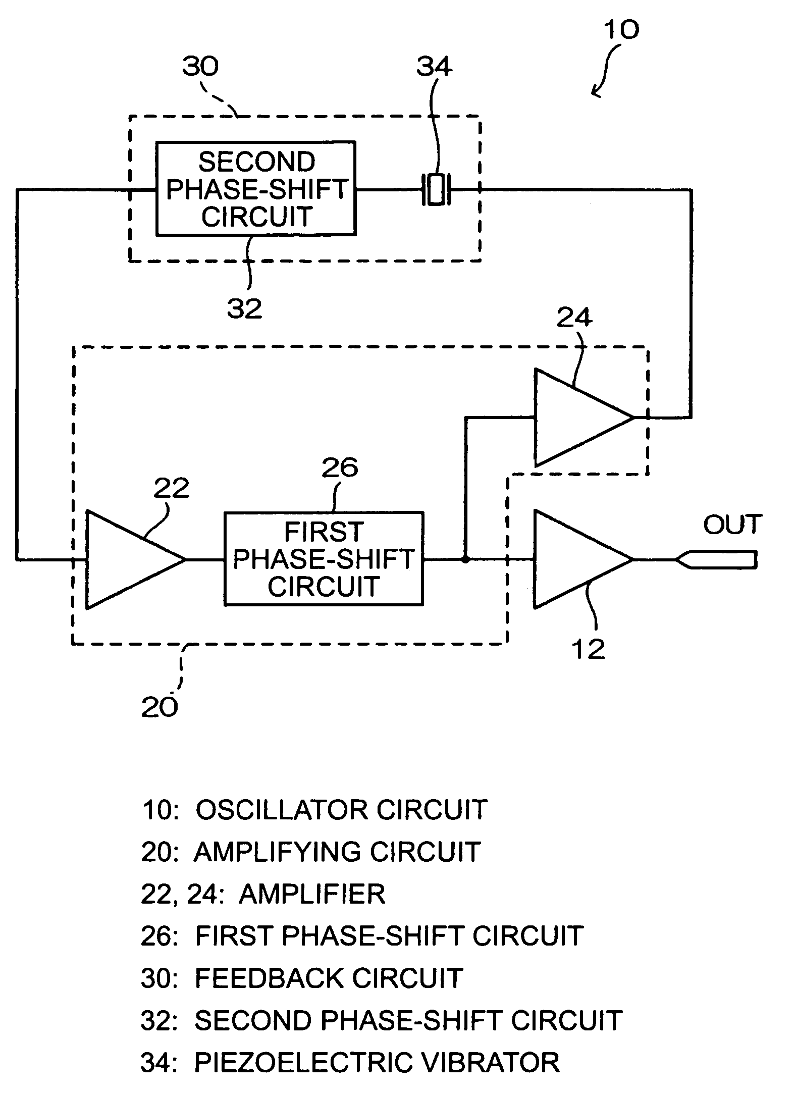
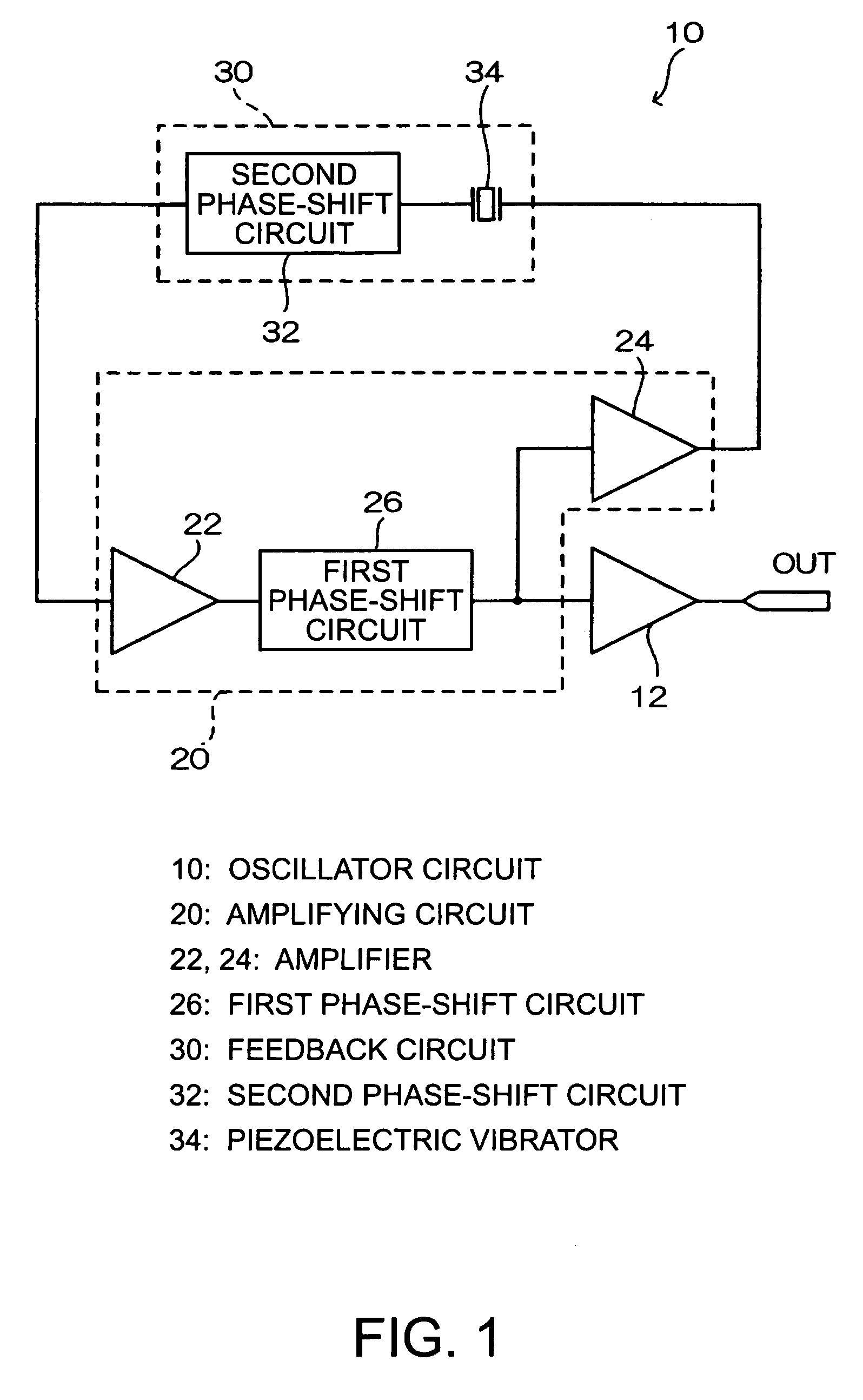
[0048]FIG. 1 is a block diagram showing an oscillator circuit 10 for a piezoelectric vibrator according to a In FIG. 1, the oscillator circuit 10 includes an amplifying circuit 20 and a feedback circuit 30. The amplifying circuit 20 includes a plurality of amplifiers 22 and 24, which also function as impedance buffers, and a first phase-shift circuit 26. The first phase-shift circuit 26 is arranged between the amplifiers 22 and 24. The input side of the first phase-shift circuit 26 is connected to the output terminal of the amplifier 22 and the output side of the first phase-shift circuit 26 is connected to the input terminal of the amplifier 24.

[0049]Also, the feedback circuit 30 includes a second phase-shift circuit 32 and a piezoelectric vibrator 34 connected to the input side of the second phase-shift circuit 32. The input side of the second phase-shift circuit 32 is connected to the output terminal of the amplifier 24 with the piezoelectric vibrator 34 therebetween. The output...

second embodiment

[0055]FIG. 7 is a block diagram showing a piezoelectric vibrator oscillator circuit 50 according to a In FIG. 7, the oscillator circuit 50 is a closed loop including the amplifying circuit 20 and a second phase-shift circuit 52 functioning as a feedback circuit. The second phase-shift circuit 52 includes a phase-shift circuit part 54, the piezoelectric vibrator 34, and a tank circuit 56. The piezoelectric vibrator 34 may be arranged on the input side of the second phase-shift circuit 52.

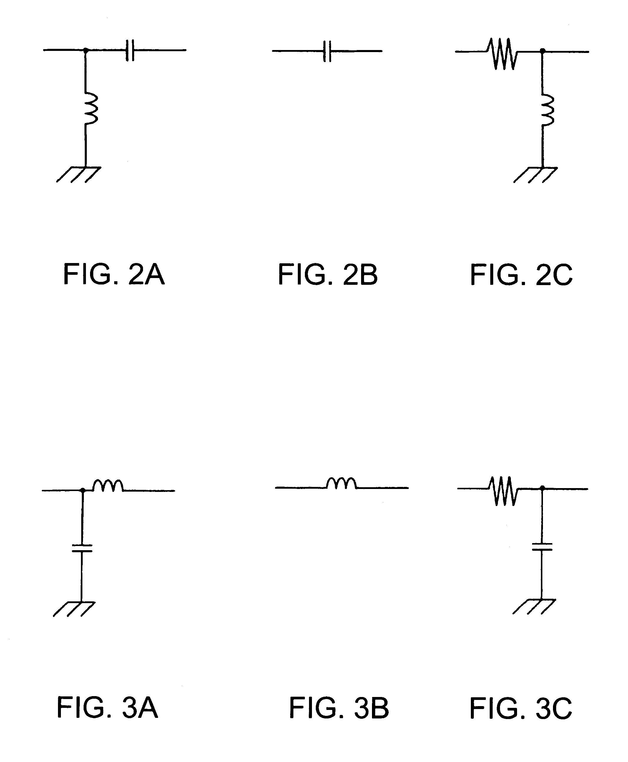
[0056]The phase-shift circuit part 54 can be arranged in a similar manner to the first phase-shift circuit 26 and the second phase-shift circuit 32 (see FIG. 1). The input side of the phase-shift circuit part 54 is connected to the output terminal of the amplifier 24 constituting the amplifying circuit 20. Also, the output side of the phase-shift circuit part 54 is connected to one electrode of the piezoelectric vibrator 34. The other electrode of the piezoelectric vibrator 34 is connected to the in...

third embodiment

[0075]In the oscillator circuit 120 arranged as described above, the two amplifiers 122 and 124 constituting the first phase-shift circuit 26 control the phase of the entire closed loop. Advantages similar to the oscillator circuit according to the embodiments described above can also be achieved in the oscillator circuit 120 according to the Here, three or more amplifiers constituting the first phase-shift circuit 26 may be provided.


PUM

PropertyMeasurementUnit
frequencyaaaaaaaaaa
frequencyaaaaaaaaaa
frequencyaaaaaaaaaa

Abstract

An oscillator circuit is a closed loop including an amplifying circuit and a feedback circuit. The amplifying circuit includes a pair of amplifiers, which also function as impedance buffers, and a first phase-shift circuit. The feedback circuit includes a second phase-shift circuit and a piezoelectric vibrator. The second phase-shift circuit is capable of adjusting the phase and gain of the feedback circuit. The first phase-shift circuit of the amplifying circuit is arranged between the pair of amplifiers and is separated, in terms of impedance, from the second phase-shift circuit. The first phase-shift circuit is capable of adjusting the phase of the entire closed loop.

Description

RELATED APPLICATIONS[0001]This application claims priority to Japanese Patent Application No. 2003-072363 filed Mar. 17, 2003 and 2004-013195 filed Jan. 21, 2004 which are hereby expressly incorporated by reference herein in their entireties.BACKGROUND[0002]1. Technical Field[0003]The present invention relates to oscillator circuits for piezoelectric vibrators, and more particularly, to an oscillator circuit suitable for causing a piezoelectric vibrator immersed in liquid to oscillate, an oscillator circuit adjusting method, and a mass measuring apparatus using the oscillator circuit.[0004]2. Background Art[0005]In recent years, quartz crystal microbalances (QCMs) using a quartz vibrator, which is a piezoelectric vibrator, have been receiving attention. QCMs utilize the fact that deposition of a substance on an electrode of a quartz vibrator reduces the oscillation frequency. Since QCMs are capable of detecting masses on the order of nanograms (ng) or less, QCMs are applied, as bios...

Claims


Application Information

Patent Timeline
Patent Type & Authority Patents(United States)
IPC IPC(8): H03B5/20G01N5/02H03B5/30H03B5/32H03B5/36H03H3/04H03H7/20H03H9/02H03H9/13H03L7/099
CPCH03B5/368H03L7/0995
Inventor KOBAYASHI, YOSHIHIRO
Owner SEIKO EPSON CORP
Why Eureka
Try Eureka