Acoustic beam forming with robust signal estimation

Inactive Publication Date: 2006-05-16
SOUND VIEW INNOVATIONS
View PDF8 Cites 49 Cited by
  • Summary
  • Abstract
  • Description
  • Claims
  • Application Information

AI Technical Summary

Benefits of technology

[0010]Other implementations of the present invention use a robust signal estimator intermediate between a median and a mean. A representative example is a trimmed mean, where some of the highest and lowest samples are excluded before taking the man of the remaining samples. Such an estimator will yield better rejection of sound originating outside the focal volume. It will also yield lower harmonic distortion of such sound.
[0011]The present invention is computationally inexpensive, and does not require knowledge of the position of the noise source. It works well on spread-out noise sources that are spread out ove

Problems solved by technology

One of the problems with a simple linear combination of signals is that it does not address the situation when noise occurs at or near one of the microphones in the array.
In a simple linear combination of signals, such noise appears in the resulting combined signal.
These techn

Method used


Image

  • Acoustic beam forming with robust signal estimation
  • Acoustic beam forming with robust signal estimation
  • Acoustic beam forming with robust signal estimation

Examples


Embodiment Construction

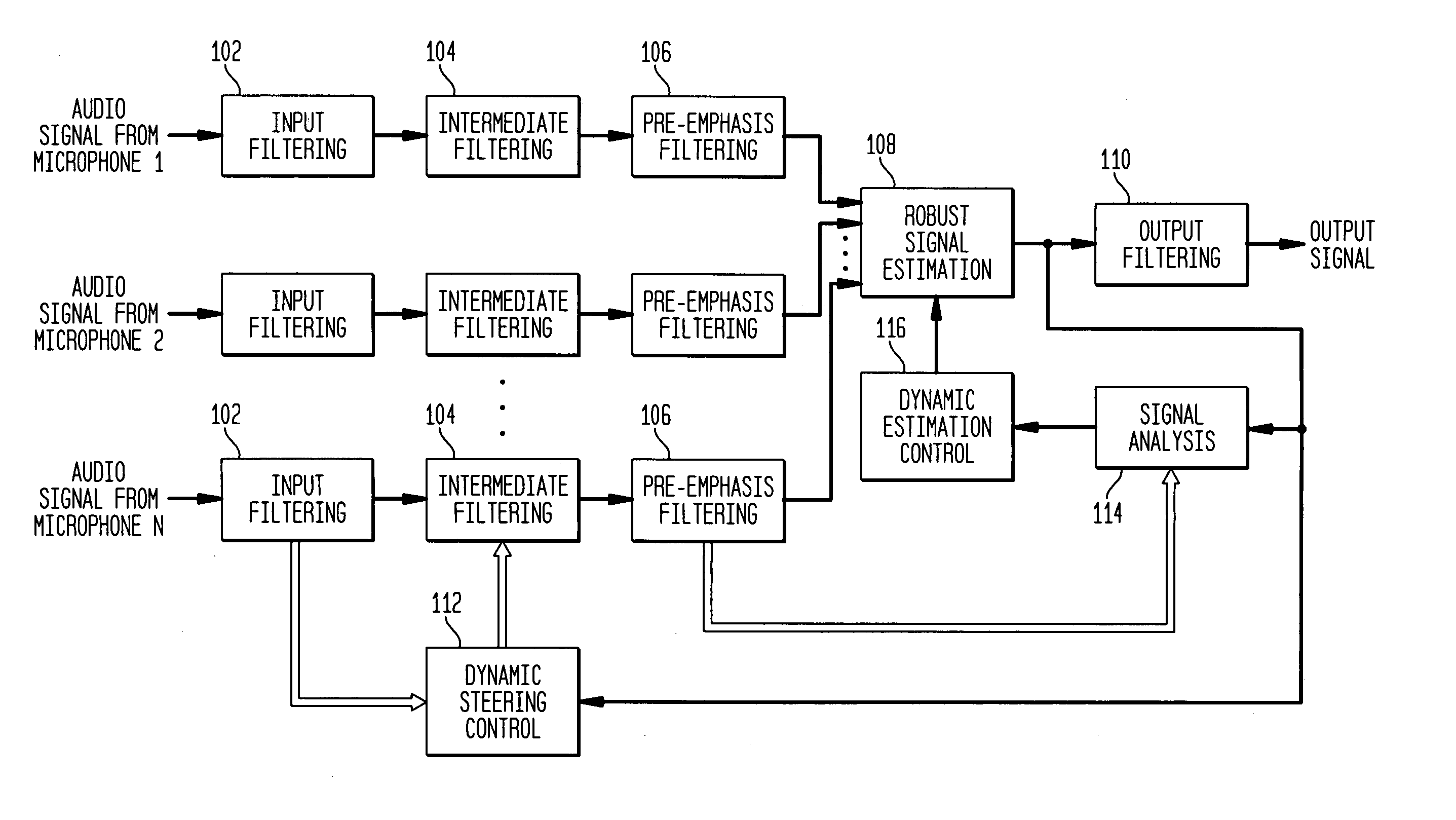
[0017]FIG. 1 shows a block diagram of audio signal processing performed to implement dynamic acoustic beam forming for an array of N microphones, according to one embodiment of the present invention. As used in this specification, the term “acoustic signal” refers to the air vibrations corresponding to actual sounds, while the term “audio signal” refers to the electrical signal generated by a microphone in response to a received acoustic signal.

[0018]As shown in FIG. 1, the audio signal generated by each microphone is independently subjected to a processing channel comprising the steps of input filtering 102, intermediate filtering 104, and pre-emphasis filtering 106. Input filtering 102, which is preferably digital filtering, matches the frequency response of the corresponding combined microphone-filter system to a desired standard. In one embodiment, intermediate filtering 104 comprises delay and scaling filtering that delays and scales the corresponding digitally filtered audio s...


PUM


Abstract

Audio signals from any array of microphones are individually filtered, delayed, and scaled in order to form an acoustic beam that focuses the array on a particular region. Nonlinear robust signal estimation processing is applied to the resulting set of audio signals to generate an output signal for the array. The nonlinear robust signal estimation processing may involve dropping or otherwise reducing the magnitude of one or more of the highest and lowest data in each set of values from the resulting audio signals and then selecting the median from or generating an average of the remaining values to produce a representative, central value for the output audio signal. The nonlinear robust signal estimation processing effectively discriminates against noise originating at an unknown location outside of the focal region of the acoustic beam.

Description

BACKGROUND OF THE INVENTION[0001]1. Field of the Invention[0002]The present invention relates to audio signal processing, and, in particular, to acoustic beam forming with an array of microphones.[0003]2. Description of the Related Art[0004]Microphone arrays can be focused onto a volume of space by appropriately scaling and delaying the signals from the microphones, and then linearly combining the signals from each microphone. As a result, signals from the focal volume add, and signals from else where (i.e., outside the focal volume) tend to cancel out.[0005]One of the problems with a simple linear combination of signals is that it does not address the situation when noise occurs at or near one of the microphones in the array. In a simple linear combination of signals, such noise appears in the resulting combined signal.[0006]These is prior art for canceling noise sources whose positions are known, such as those based on radar jamming countermeasures, where the delays and scales of ...

Claims


Application Information

Patent Timeline
IPC IPC(8): H04R3/00
CPCH04R3/005H04R2430/20
Inventor KOCHANSKI, GREGORY P.SONDHI, MAN M.
Owner SOUND VIEW INNOVATIONS
Why Eureka
Try Eureka