Apparatus for and method of controlling air-fuel ratio of internal combustion engine, and recording medium storing program for controlling air-fuel ratio of internal combustion engine

Inactive Publication Date: 2006-05-23
HONDA MOTOR CO LTD
View PDF7 Cites 27 Cited by
  • Summary
  • Abstract
  • Description
  • Claims
  • Application Information

AI Technical Summary

Benefits of technology

[0048]With the above arrangement, the estimated value of the temperature of the heater can be determined accurately in the same manner as the temperature of the active element is estimated. Thus, the matching between the target value for the output of the exhaust gas sensor that is set depending on the estimated value of the temperature of the heater and the actual temperature of the active element can be increased, making it possible to maintain more appropriately the desired exhaust gas purifying capability of the catalytic converter. The data for use as the heater energy supplied quantity data, the form of the thermal model, and the parameter representative of the operating state of the internal combustion engine may be the same as those of the first aspect of the present invention.
[0049]To increase the accuracy of the estimated value of the temperature of the heater, the estimated value of the temperature of the exhaust gas that is used to dete

Problems solved by technology

Therefore, in the case where the temperature of the sensitive element of the O2 sensor is easily variable due to the exhaust system layout or an operating state of the internal combustion engine, if the target value for the output of the O2 sensor is se

Method used


Image

  • Apparatus for and method of controlling air-fuel ratio of internal combustion engine, and recording medium storing program for controlling air-fuel ratio of internal combustion engine
  • Apparatus for and method of controlling air-fuel ratio of internal combustion engine, and recording medium storing program for controlling air-fuel ratio of internal combustion engine
  • Apparatus for and method of controlling air-fuel ratio of internal combustion engine, and recording medium storing program for controlling air-fuel ratio of internal combustion engine

Examples


Embodiment Construction

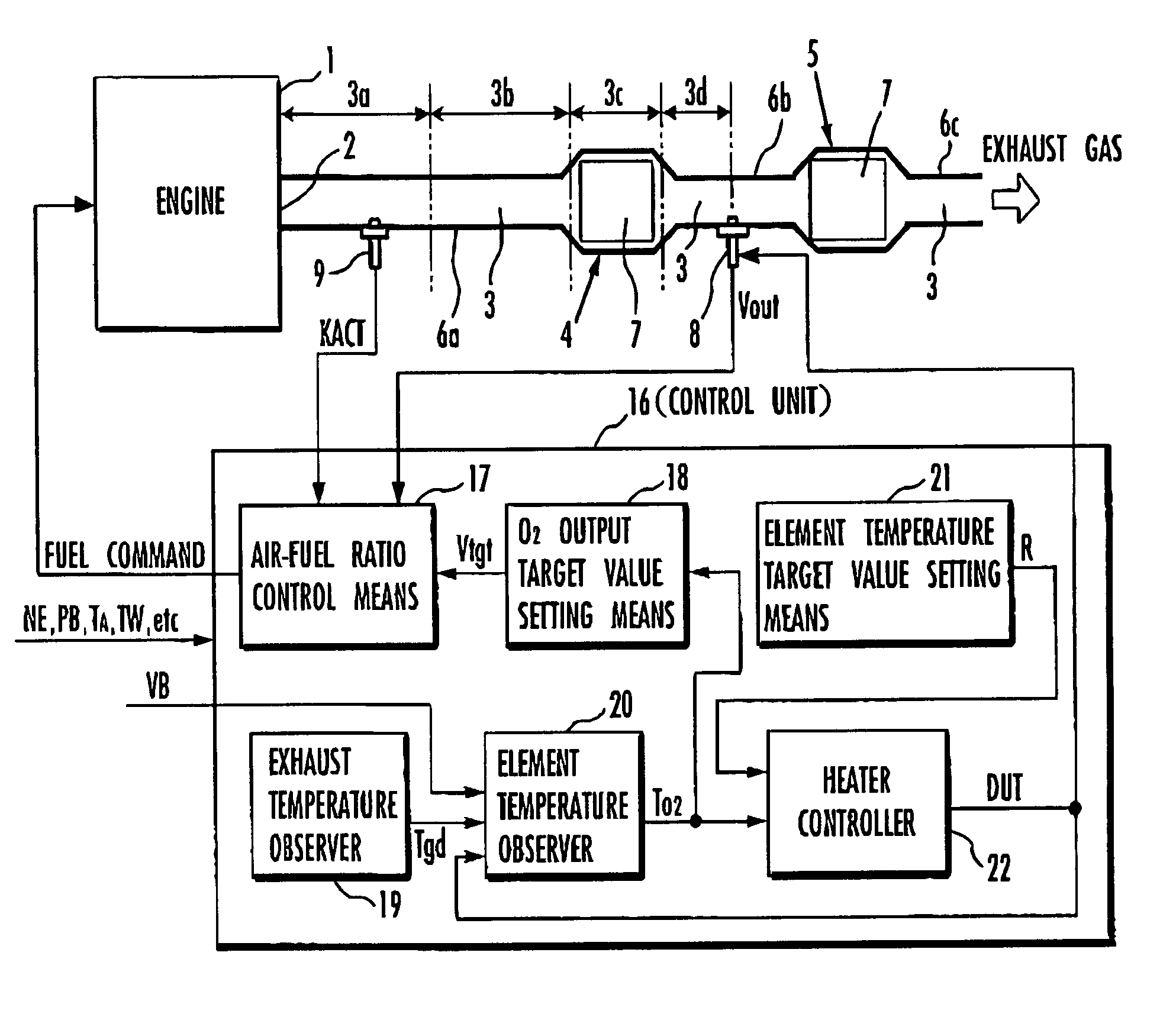
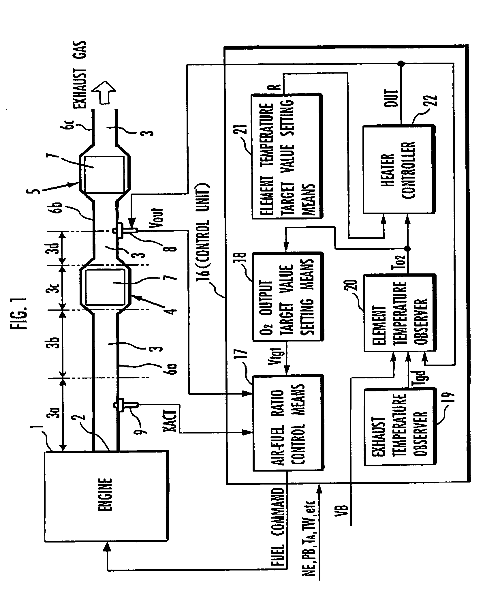
[0078]An apparatus for controlling the air-fuel ratio of an internal combustion engine according to a first embodiment of the present invention will be described below with reference to FIGS. 1 through 12. The first embodiment of the present invention corresponds to a first aspect of the present invention. FIG. 1 shows in block form an overall arrangement of the apparatus according to the first embodiment of the present invention. In FIG. 1, an engine (an internal combustion engine) 1 mounted on an automobile, a hybrid vehicle, or the like combusts a mixture of fuel and air and generates an exhaust gas, which is discharged into the atmosphere through an exhaust passage 3 communicating with an exhaust port 2 of the engine 1. The exhaust passage 3 incorporates therein two catalytic converters 4, 5 disposed successively downstream for purifying the exhaust gas emitted from the engine 1 and flowing through the exhaust passage 3. The exhaust passage 3 includes a section upstream of the c...


PUM


Abstract

A target value Vtgt for an output Vout of an O2 sensor 8 (an exhaust gas sensor) disposed downstream of a catalytic converter 4 is set variably depending on a temperature TO2 of an active element 10 of the O2 sensor 8 by a target value setting unit 18, and the air-fuel ratio of an exhaust gas is controlled by an air-fuel ratio control unit 17 to converge the output Vout to the target value Vtgt. An exhaust gas temperature Tgd is estimated by an exhaust temperature observer 19, and the temperature TO2 of the active element 10 is sequentially estimated by an element temperature observer 20 using the estimated value of the exhaust gas temperature Tgd. A heater 13 of the O2 sensor 8 is controlled by a heater controller 22 to keep the temperature TO2 of the active element 10 at a predetermined target value R. The air-fuel ratio is thus controlled to maintain a desired exhaust gas purifying capability of the catalytic converter irrespective of the temperature of the active element of the exhaust gas sensor.

Description

BACKGROUND OF THE INVENTION[0001]1. Field of the Invention[0002]The present invention relates to an apparatus for and a method of controlling the air-fuel ratio of an internal combustion engine, and a recording medium storing a program for controlling the air-fuel ratio of an internal combustion engine.[0003]2. Description of the Related Art[0004]Heretofore, it has been known in the art to place an exhaust sensor downstream of a catalytic converter that is disposed in the exhaust passage of an internal combustion engine, the exhaust sensor having a sensitive element that is sensitive to a certain component of the exhaust gas, and control the air-fuel ratio of the exhaust gas that is supplied from the internal combustion engine to the catalytic converter in order to converge an output of the exhaust gas sensor to a predetermined target value for the purpose of achieving a desired exhaust gas purifying capability of the catalytic converter. For example, Japanese laid-open patent publi...

Claims


Application Information

Patent Timeline
IPC IPC(8): F01N3/00F02D45/00F02D41/14
CPCF02D41/1494F02D41/1473F02D41/1454F02D41/1446
Inventor YASUI, YUJI
Owner HONDA MOTOR CO LTD
Why Eureka
Try Eureka