Diesel engine control system with optimized fuel delivery

a technology of engine control system and fuel delivery, which is applied in the direction of electric control, speed sensing governor, speed sensing device, etc., can solve the problems of excessive amount of smoke the operation of the locomotive exceeding allowable emission standards, and the amount of power produced by the engine. it does nothing to increase the power produced by the engine, so as to promote efficient combustion of fuel and optimize fuel delivery

Inactive Publication Date: 2006-05-23
GENERAL ELECTRIC CO
View PDF22 Cites 43 Cited by
  • Summary
  • Abstract
  • Description
  • Claims
  • Application Information

AI Technical Summary

Benefits of technology

[0012]Briefly stated, the present invention relates to a method of controlling fuel delivery to a locomotive's diesel engine so to optimize fuel delivery and promote efficient combustion of the fuel, maximize engine performance, and reduce emissions. Importantly, the method provides both a dynamic response to changes in operation and a learning capability by which an engine's control system becomes uniquely adapted to the particular engine, over time.
[0013]The method employs three interrelated engine control loops by which a desired level of fuel needed by the engine is determined based upon engine operating parameters. A first loop utilizes factors related to engine speed. A second loop utilizes factors related to fuel demand and employs Taylor series functions. A separate Taylor series is utilized for each parameter used to determine engine performance for each set of engine operating conditions, and these coefficients are modified, over time, to the particular engine so as to be unique for that engine. The third loop takes inputs from the other two loops and combines them with other information to optimize engine performance and reduce emissions.
[0014]By controlling fuel delivery in response to the control method of the invention, the engine's output power is maximized for a given operating speed, better fuel delivery is achieved, the amount of smoke in the engine's exhaust is minimized, and other emissions' levels are reduced. This, in turn, allows the engine's operation to be controlled for peak performance for a given set of operating conditions, while reducing engine operating costs.

Problems solved by technology

This results in an excessive amount of smoke being produced by the engine.
Excessive smoke will result in the locomotive's operation exceeding allowable emission standards.
As importantly, delivering too much fuel to the engine does nothing to increase to the amount of power (torque) produced by the engine.
This results in a loss of power and reduces the engine's efficiency.
There is also a substantial increase in the cost of operating the locomotive because of the fuel being wasted, especially since the engine obtains no benefit from the oversupply of fuel.

Method used


Image

  • Diesel engine control system with optimized fuel delivery
  • Diesel engine control system with optimized fuel delivery
  • Diesel engine control system with optimized fuel delivery

Examples


Embodiment Construction

[0020]The following detailed description illustrates the invention by way of example and not by way of limitation. The description clearly enables one skilled in the art to make and use the invention, describes several embodiments, adaptations, variations, alternatives, and uses of the invention, including what is presently believed to be the best mode of carrying out the invention.

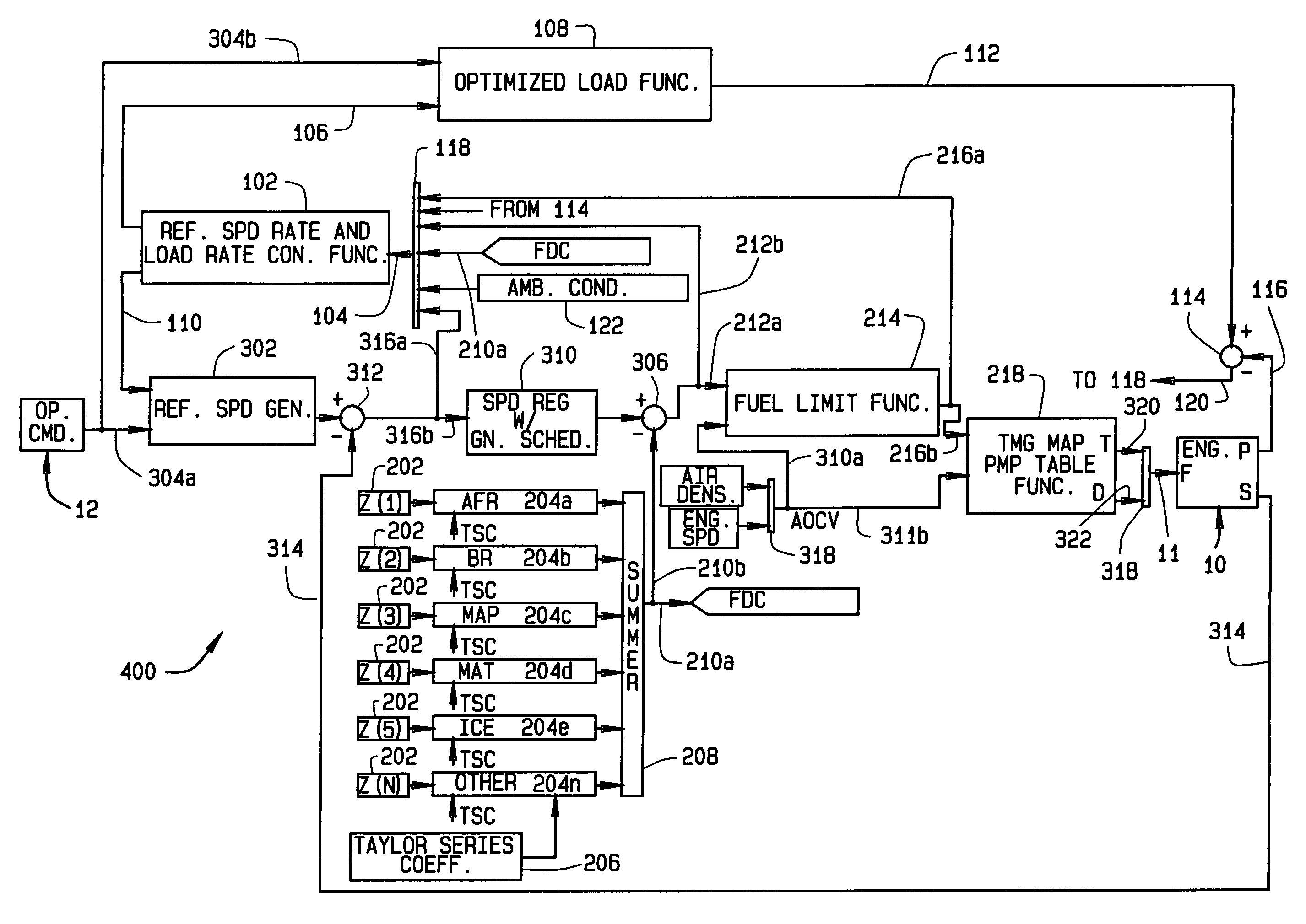
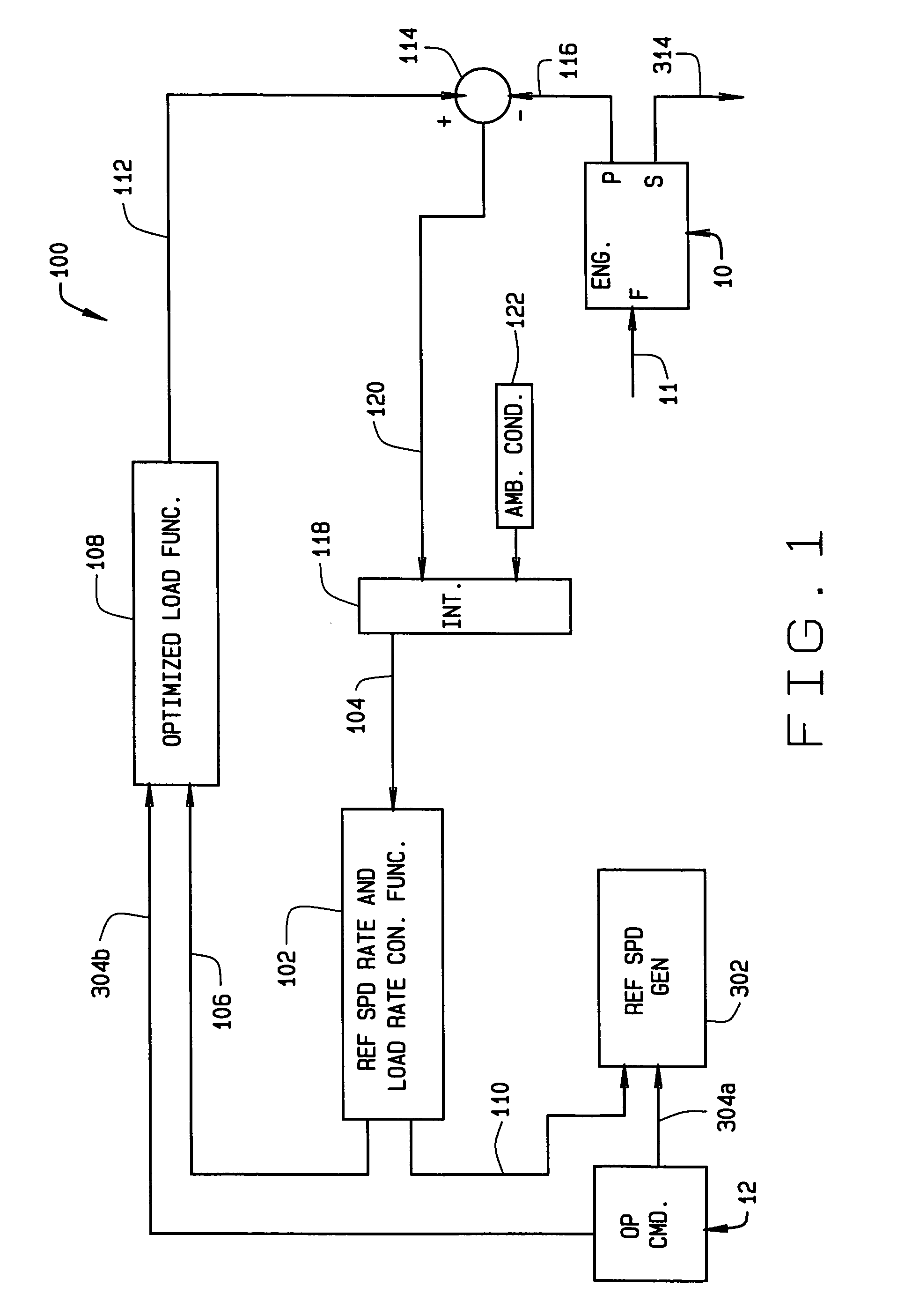
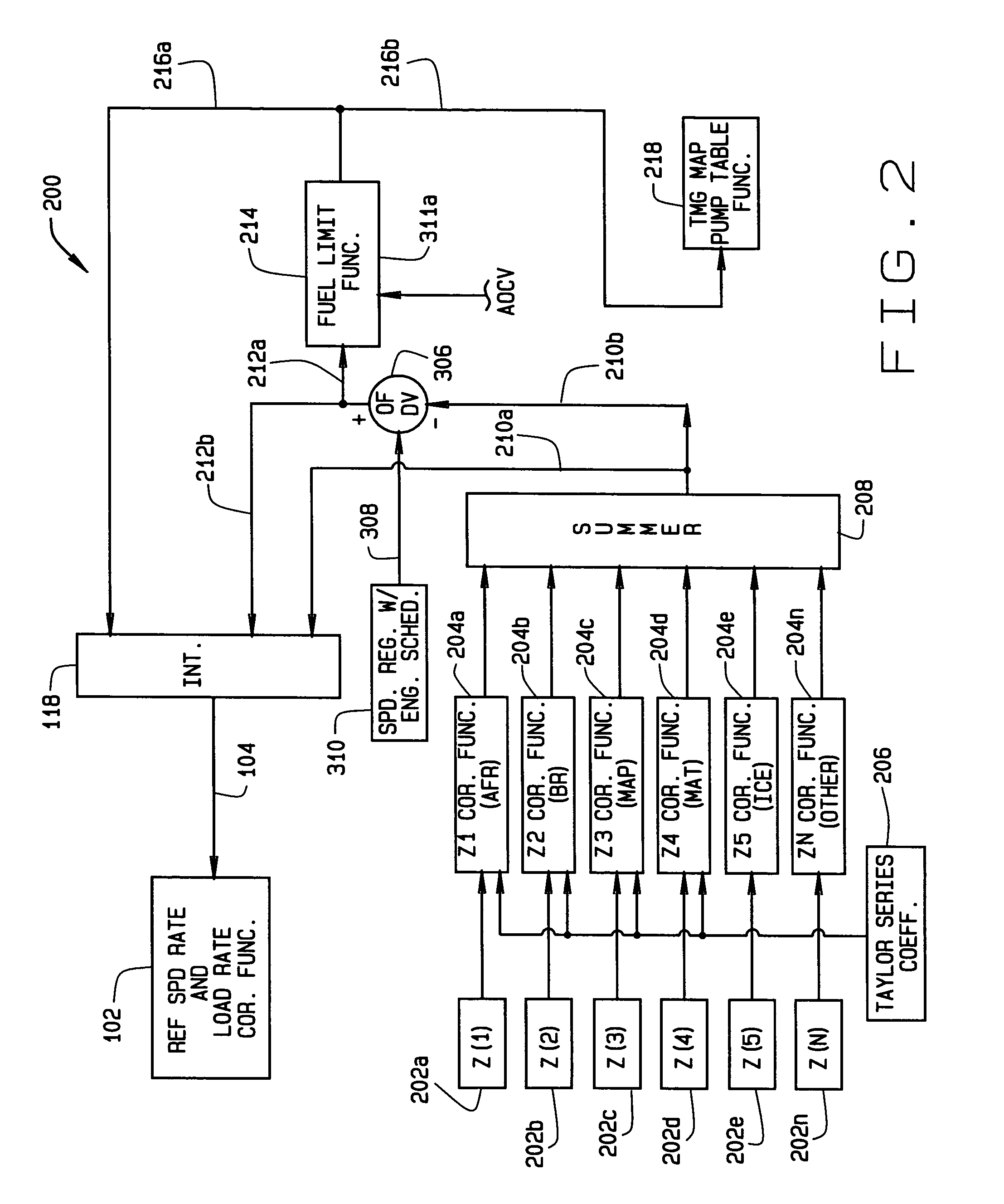
[0021]Referring to the drawings, the system and method of the present invention employ an architecture for dynamically controlling operation of a locomotive diesel engine 10. The architecture consists of two inner control loops indicated generally 100 and 200 respectively, and an outer loop indicated generally 300. Loop 100, which is shown in FIG. 1, generally comprises a primary feedback control consisting of a proportional, integral type controller with gain scheduling. This loop functions to regulate engine speed to a commanded slew rate based upon commands from an operator of engine 10. Second loop 20...


PUM


Abstract

A system (400) and method of determining fuel demands of a locomotive engine (10) based upon engine speed and power produced by the engine at a given time, so to optimize the engine's power output for a load while reducing engine emissions. The engine control architecture comprises three interrelated control loops (100–300). A primary feedback control loop (100) employs integral type control with gain scheduling to regulate engine speed to commanded slew rated based upon the locomotive's operator commands. A second control loop (200) provides an active, feed forward or predictive control consisting of a plurality of correction functions each utilizing a Taylor series having coefficients for each term in the series, the coefficients being modified to adapt the system to the engine with which it is used. A control third loop (300) optimizes reference speed slew rates and engine load rates by providing feedback of nominal engine fuel requirements or fuel demand, corrections to fuel demand based upon outputs from the second control loop, speed error values, and ambient conditions.

Description

CROSS-REFERENCE TO RELATED APPLICATIONS[0001]None.STATEMENT REGARDING FEDERALLY SPONSORED RESEARCH OR DEVELOPMENT[0002]Not Applicable.BACKGROUND OF THE INVENTION[0003]This invention relates to diesel powered locomotives; and more particularly, to a system and a method controlling the supply of fuel to the locomotive's engine. The method utilizes speed and load information for the engine, and other engine operating information, to dynamically react to changes in engine load or other conditions which impact the engine's fuel requirements, predict fuel demand in response to these changes so to control engine speed, optimize the power output of the engine, prevent oversupply of fuel to the engine, and substantially reduce residual smoke and other regulated emissions the engine may produce. The system and method employ an adaptive capability by which, over time, coefficients utilized in producing the dynamic response are optimized for the particular engine and the environment in which th...

Claims


Application Information

Patent Timeline
Patent Type & Authority Patents(United States)
IPC IPC(8): F02D31/00F02D41/14
CPCF02D41/1402F02D2041/1419F02D2041/1418F02D2041/141
Inventor FLYNN, PAULDAUM, WOLFGANGSHEIKH, AHMED
Owner GENERAL ELECTRIC CO
Why Eureka
Try Eureka