Vehicle mobile work station

a work station and vehicle technology, applied in the direction of roofs, transportation items, transportation and packaging, etc., can solve the problem of not providing a platform that can function as a fully integrated mobile work spa

Active Publication Date: 2006-05-23
FCA US
View PDF25 Cites 70 Cited by
  • Summary
  • Abstract
  • Description
  • Claims
  • Application Information

AI Technical Summary

Problems solved by technology

While these storage systems may be adequate for their intended use, they do no

Method used


Image

  • Vehicle mobile work station
  • Vehicle mobile work station
  • Vehicle mobile work station

Examples


Embodiment Construction

[0015]The following description of the preferred embodiment(s) is merely exemplary in nature and is in no way intended to limit the invention, its application, or uses.

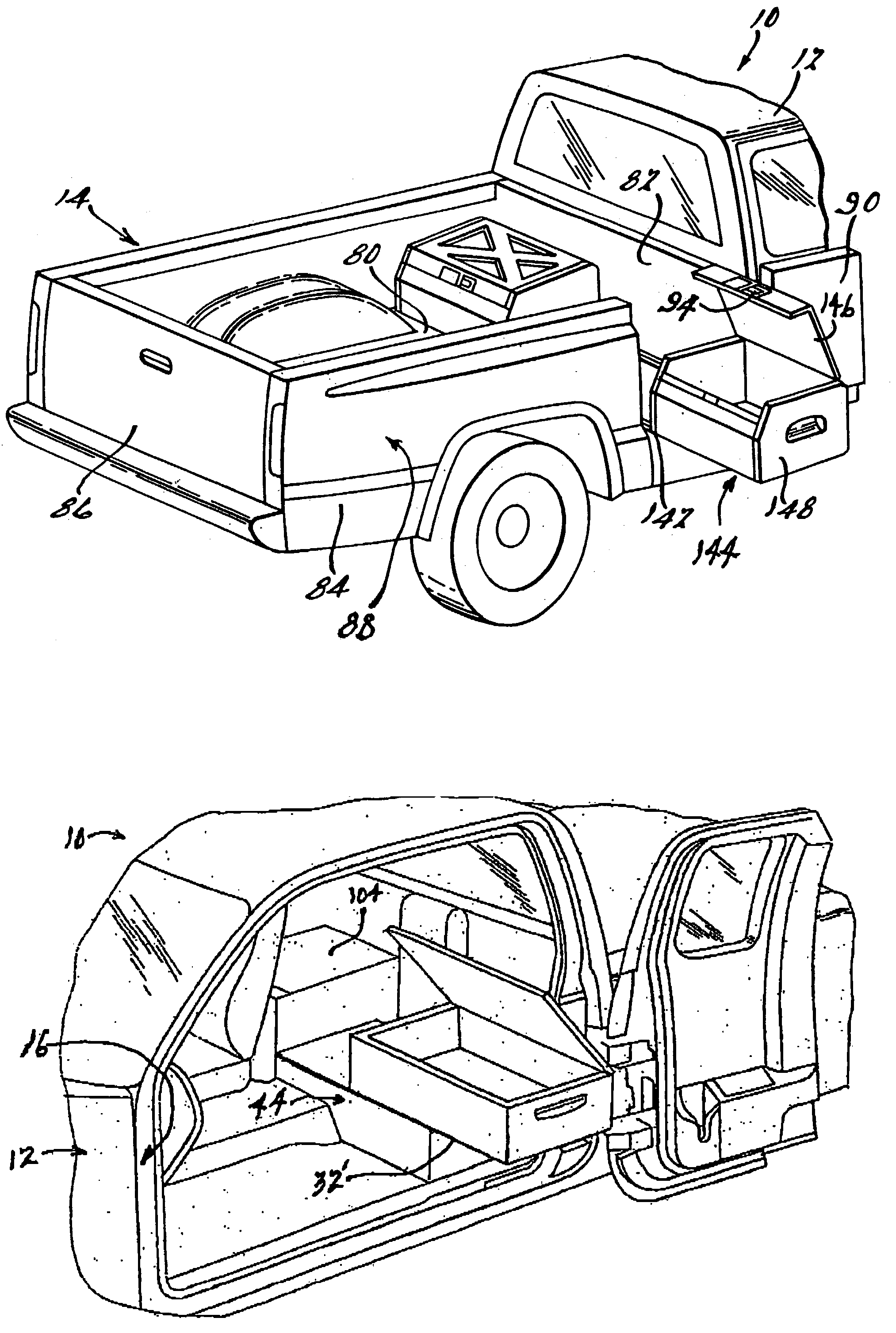
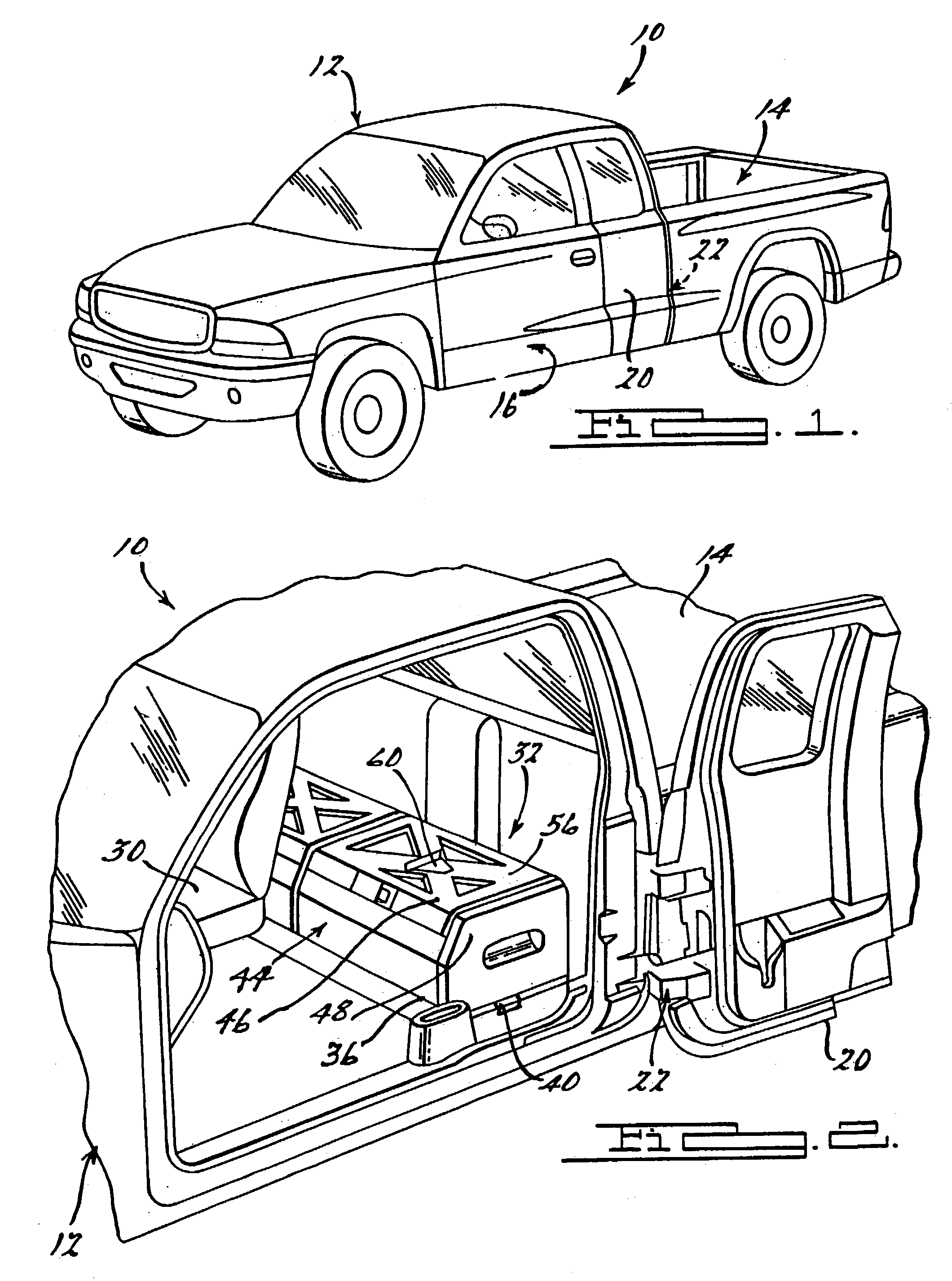
[0016]FIG. 1 illustrates a vehicle 10 including a cab 12 and a bed 14. Preferably, vehicle 10 is an extended cab truck. Cab 12 includes an outer surface 16 defining an exterior plane of vehicle 10 and an access door 20 coupled to cab 12 by hinges 22. Access door 20 rotates about the axes of hinges 22 from a closed position to an open position.

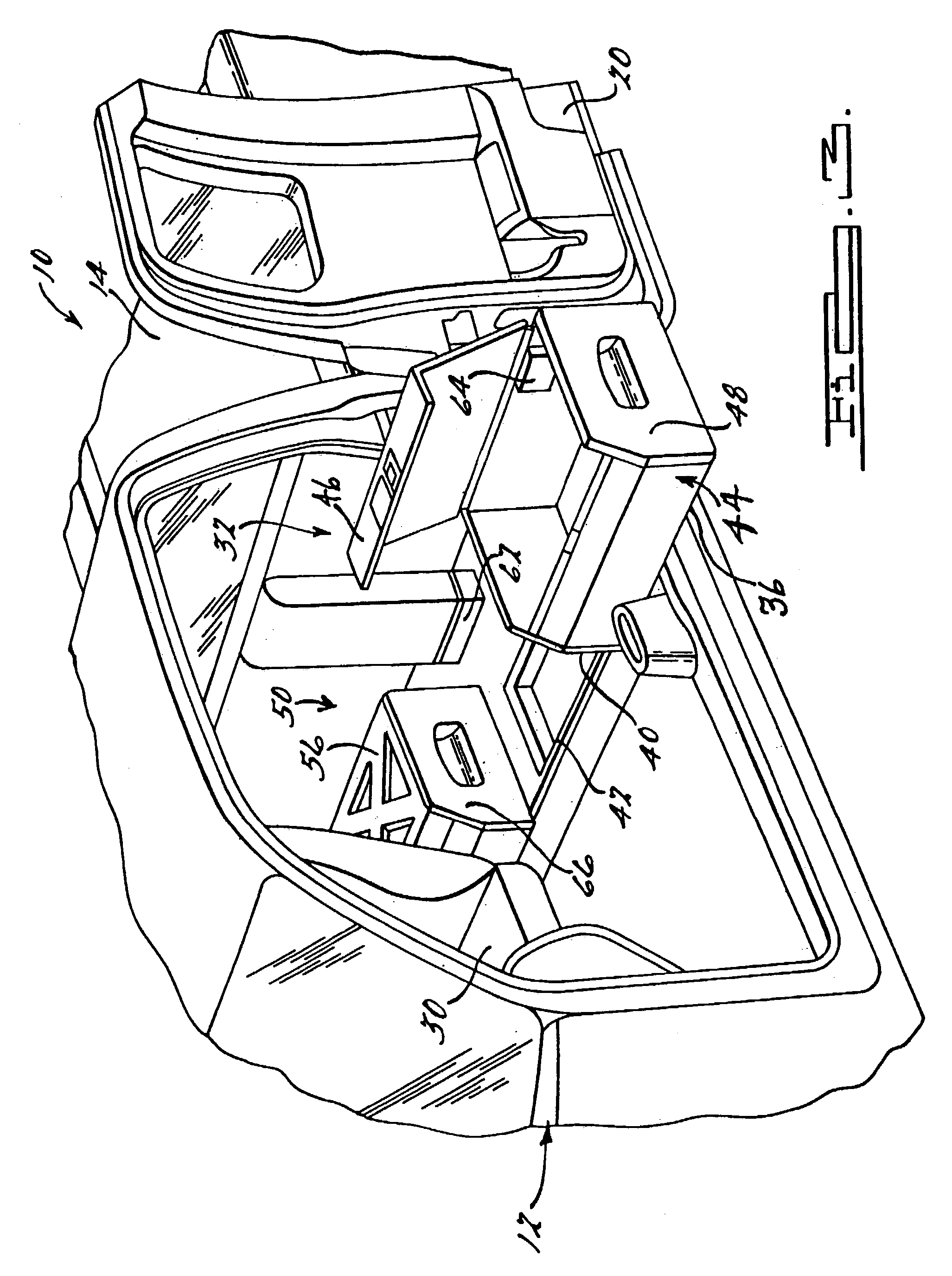
[0017]With reference to FIGS. 2 and 3, cab 12 also includes a work station 32 located behind seats 30. Work station 32 includes a load floor 36, a catch mechanism 40, and a sliding mechanism 42. Sliding mechanism 42 is interposed between load floor 36 and cab 12, and allows load floor 36 to move between a stowed position (FIG. 2), wherein load floor 36 is located within cab 12, and an extended position (FIG. 3), wherein at least a portion of load floor 36 extends beyond a plane d...


PUM


Abstract

A mobile work station assembly for a vehicle. The work station incorporates a docking station, toolbox, file organizer, power inverter, storage container and a mobile phone assembly on a sliding load floor that can extend outwardly from the interior of the vehicle. The work station is removably attached to the load floor. The work station is adapted for mounting in a vehicle interior or within a pickup truck bed.

Description

FIELD OF THE INVENTION[0001]The present invention relates to mobile vehicle mounted work stations.BACKGROUND OF THE INVENTION[0002]Consumer demand has led to the development of vehicles that provide versatility for different uses. U.S. Pat. No. 5,964,492 discloses a storage container for a pickup truck bed that is equipped to slide over the tailgate in order to provide greater access to the items stored in the container. U.S. Pat. No. 6,161,896 discloses a rear seat storage system for an automobile. While these storage systems may be adequate for their intended use, they do not provide a platform that can function as a fully integrated mobile work space. What is needed is a versatile platform that is accessible from the side of the vehicle and can function as a storage system and a mobile work space.SUMMARY OF THE INVENTION[0003]In accordance with the teachings of the present invention, a mobile work station and storage system is disclosed. In one form, the present invention provide...

Claims


Application Information

Patent Timeline
IPC IPC(8): B60N3/12B60R7/02
CPCB60R7/02
Inventor RUBEL, AARONGIEM, BRETTLEWIS, STEPHEN JREED, DAVID BKRUK, VICTOR
Owner FCA US
Why Eureka
Try Eureka