EUV lithography reticles fabricated without the use of a patterned absorber

a technology of ultraviolet lithography and absorber, which is applied in the direction of printers, instruments, and therapy, can solve the problems of difficult confinement of the affected region to a small area, the absorber edges are sharp, and the process is expensive and difficult to achieve. , to achieve the effect of increasing the miniaturization of electronic devices, significant commercial potential, and reasonable cost of ownership

Inactive Publication Date: 2006-05-23
EUV
View PDF4 Cites 9 Cited by
  • Summary
  • Abstract
  • Description
  • Claims
  • Application Information

AI Technical Summary

Benefits of technology

[0016]There is a strong commercial driving force for increased miniaturization in electronic devices, and hence an extreme ultraviolet lithography (EUVL) tool has significant commercial potential. For EUVL to be commercially viable the

Problems solved by technology

There are significant costs and issues associated with this process.
There are disadvantages with this approach, including the sharpness of the absorber edges that are produced.
The main d

Method used


Image

  • EUV lithography reticles fabricated without the use of a patterned absorber
  • EUV lithography reticles fabricated without the use of a patterned absorber
  • EUV lithography reticles fabricated without the use of a patterned absorber

Examples


Embodiment Construction

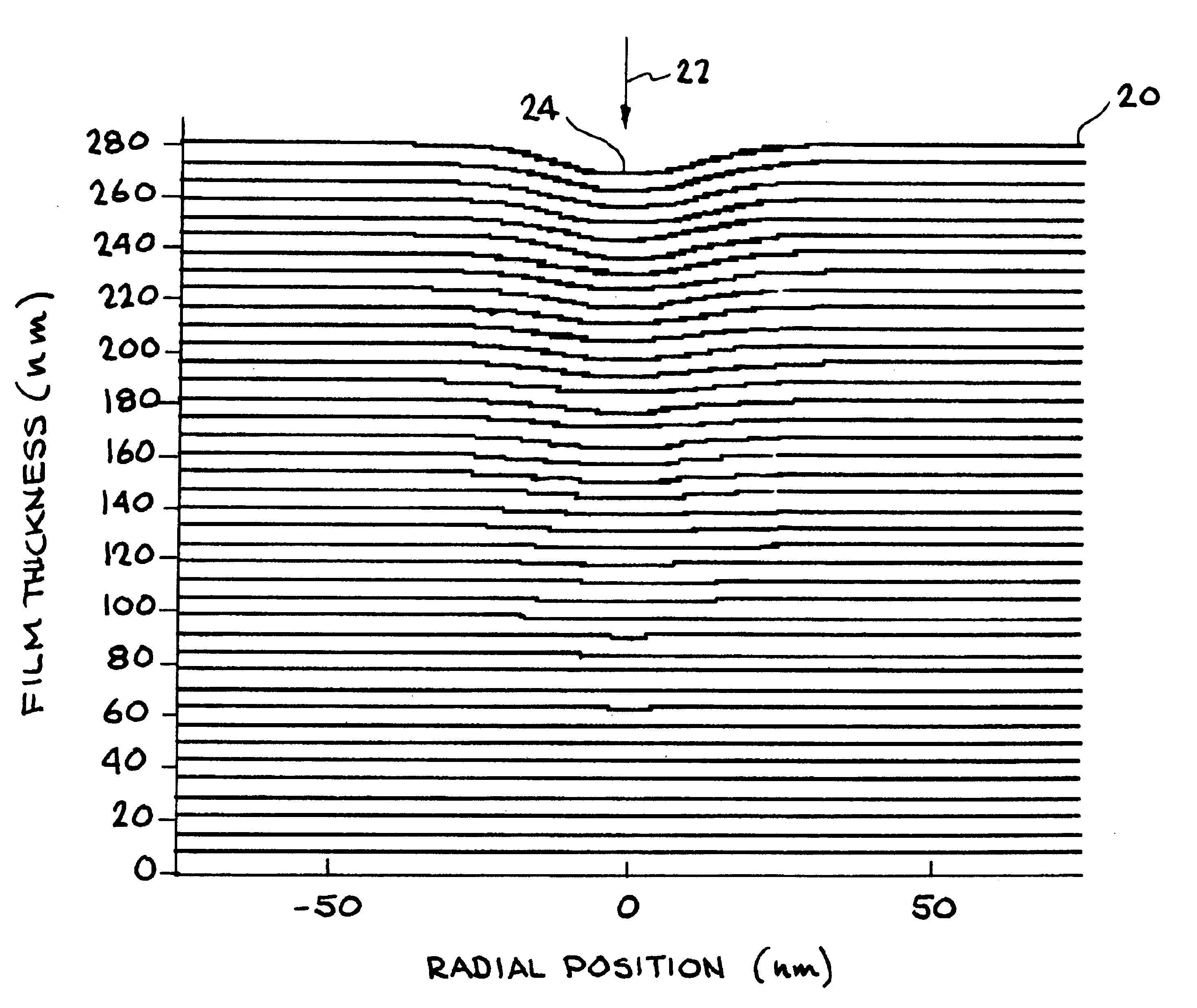
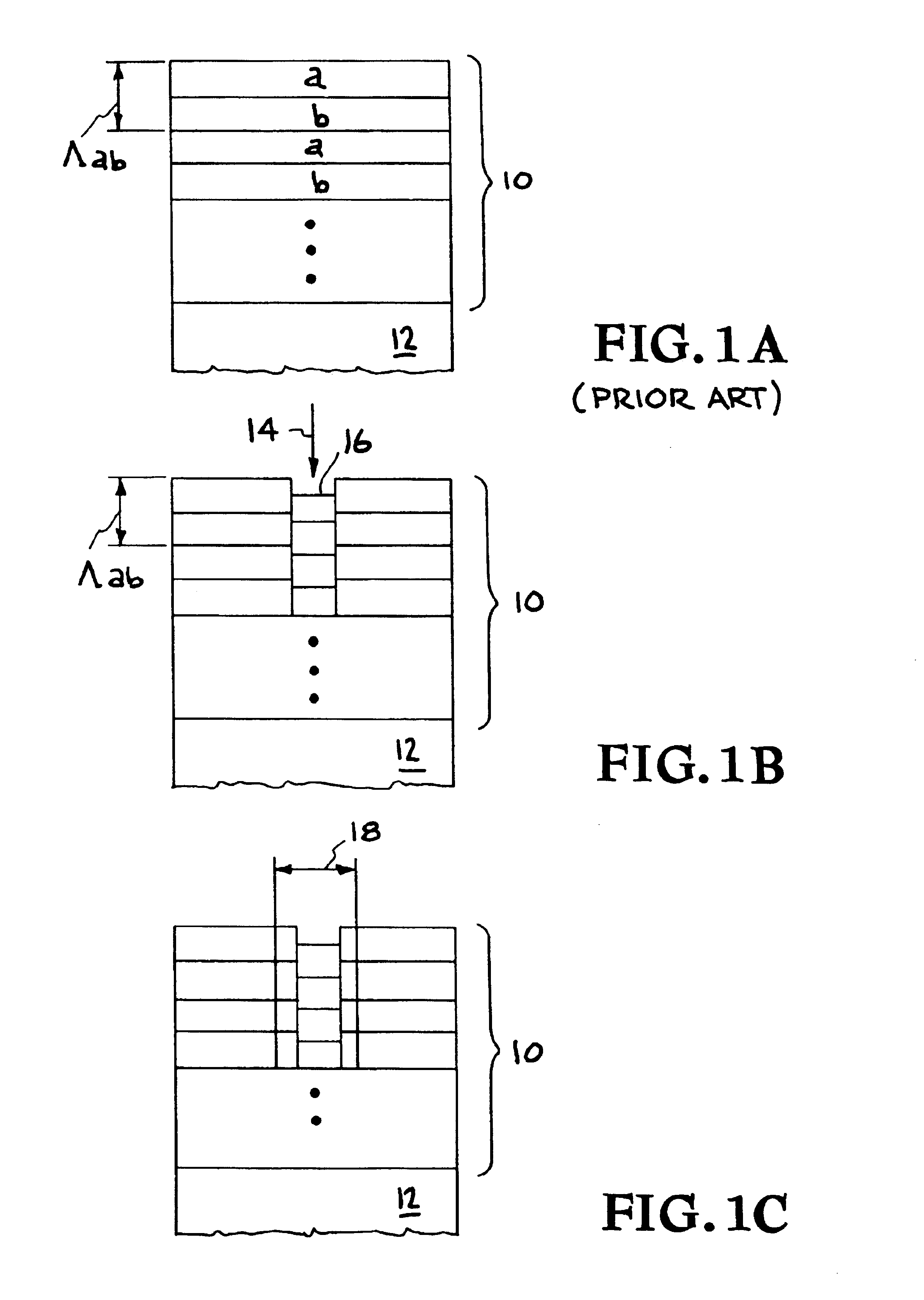
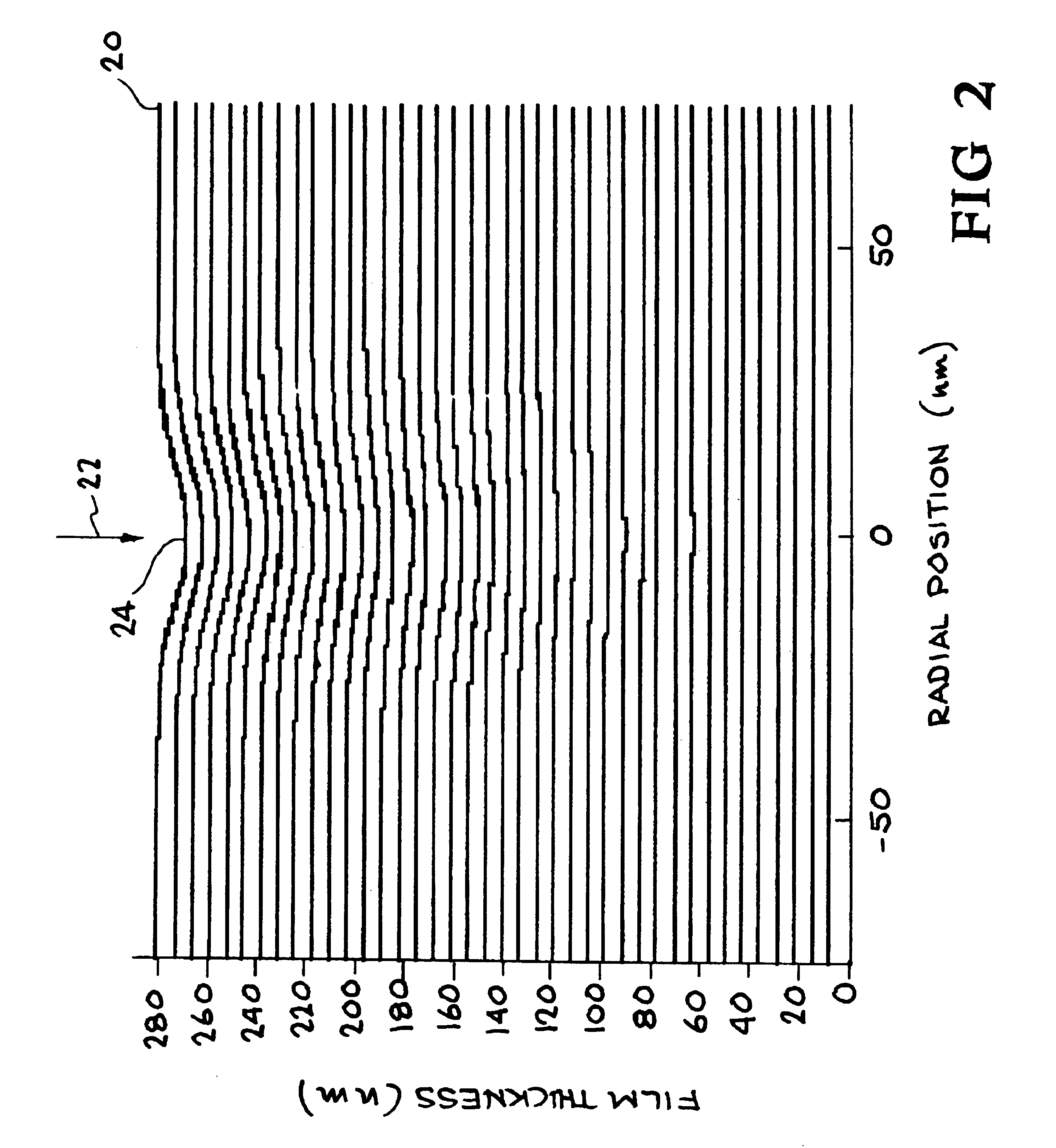
[0024]This invention eliminates the need for an absorber material in reticles for extreme ultraviolet lithography (EUVL) by introducing a direct modulation in the complex-valued reflectance of the multilayer. The reticle pattern is directly written onto the reflective multilayer coating with a spatially localized energy source such as a focused electron or ion beam. FIG. 1A shows a typical prior art reticle blank consisting of an A / B multilayer film 10 on a substrate 12, and FIG. 1B shows a reticle blank after processing with a localized energy source, which is a focused beam in this example. The focused beam 14 activates interdiffusion within the film 16 that causes the multilayer period to contract in the exposed regions. The contraction is accurately determined by the energy dose. The spatial modulation of the multilayer period produces a controllable variation in the phase and amplitude of the reflected field in the reticle plane. In an A / B multilayer-coated EUVL reticle blank, ...


PUM


Abstract

Absorber material used in conventional EUVL reticles is eliminated by introducing a direct modulation in the complex-valued reflectance of the multilayer. A spatially localized energy source such as a focused electron or ion beam directly writes a reticle pattern onto the reflective multilayer coating. Interdiffusion is activated within the film by an energy source that causes the multilayer period to contract in the exposed regions. The contraction is accurately determined by the energy dose. A controllable variation in the phase and amplitude of the reflected field in the reticle plane is produced by the spatial modulation of the multilayer period. This method for patterning an EUVL reticle has the advantages (1) avoiding the process steps associated with depositing and patterning an absorber layer and (2) providing control of the phase and amplitude of the reflected field with high spatial resolution.

Description

[0001]This is a Continuation of U.S. patent application Ser. No. 09 / 752,887, now U.S. Pat. No. 6,635,391, titled “A Method For Fabricating Reticles For EUV Lithography Without The Use Of A Patterned Absorber” filed Dec. 28, 2000, incorporated herein by reference.[0002]The United States Government has rights in this invention pursuant to Contract No. W-7405-ENG-48 between the United States Department of Energy and the University of California for the operation of Lawrence Livermore National Laboratory.BACKGROUND OF THE INVENTION[0003]1. Field of the Invention[0004]The present invention relates to the production of reticles for extreme ultraviolet lithography, and more specifically, it relates to systems and methods for directly writing patterns onto the reflective multilayer coating of an extreme ultraviolet lithography reticle.[0005]2. Description of Related Art[0006]The standard reflective reticle blank for extreme ultraviolet lithography (EUVL) consists of a thick substrate coated...

Claims


Application Information

Patent Timeline
IPC IPC(8): G03F9/00A61N5/00G03B27/00G03F1/24G03F1/34
CPCB82Y10/00G03F1/34G03F1/24B82Y40/00
Inventor STEARNS, DANIEL G.SWEENEY, DONALD W.MIRKARIMI, PAUL B.
Owner EUV
Why Eureka
Try Eureka