Downhole chemical delivery system for oil and gas wells

Active Publication Date: 2006-05-23
TECHNISAND
View PDF21 Cites 174 Cited by
  • Summary
  • Abstract
  • Description
  • Claims
  • Application Information

AI Technical Summary

Benefits of technology

[0014]The invention is the use of a dissolvable shell composition encasing a material or apparatus, that provides mech

Problems solved by technology

Both methods have substantial drawbacks.
In many cases this is not desirable.
The use of coiled tubing solves many of these problems, but the cost and risk of hanging a small diameter tube into a wellbore is substantial.
Also, corrosive attack of this coiled tubing from injected chemicals is often particularly severe, as the pipe walls tend to be thin compared to the well tubulars.
Accordingly, many of the problems associated with injecting fluids are present.
In certain wells, particularly deep and hot wells, wax encasement is not particularly useful.
Furthermore, as the temperature increases, some temperature-activated or temperature-sensitive chemicals exposed by the degradation of the wax to fluids in the wellbore may react prematurely.
Occasionally, especially when fluids had been circulated to the bottom of the wellbore or displaced into the producing formation, thereby cooling the wellbore

Method used


Image

  • Downhole chemical delivery system for oil and gas wells
  • Downhole chemical delivery system for oil and gas wells
  • Downhole chemical delivery system for oil and gas wells

Examples


example 1

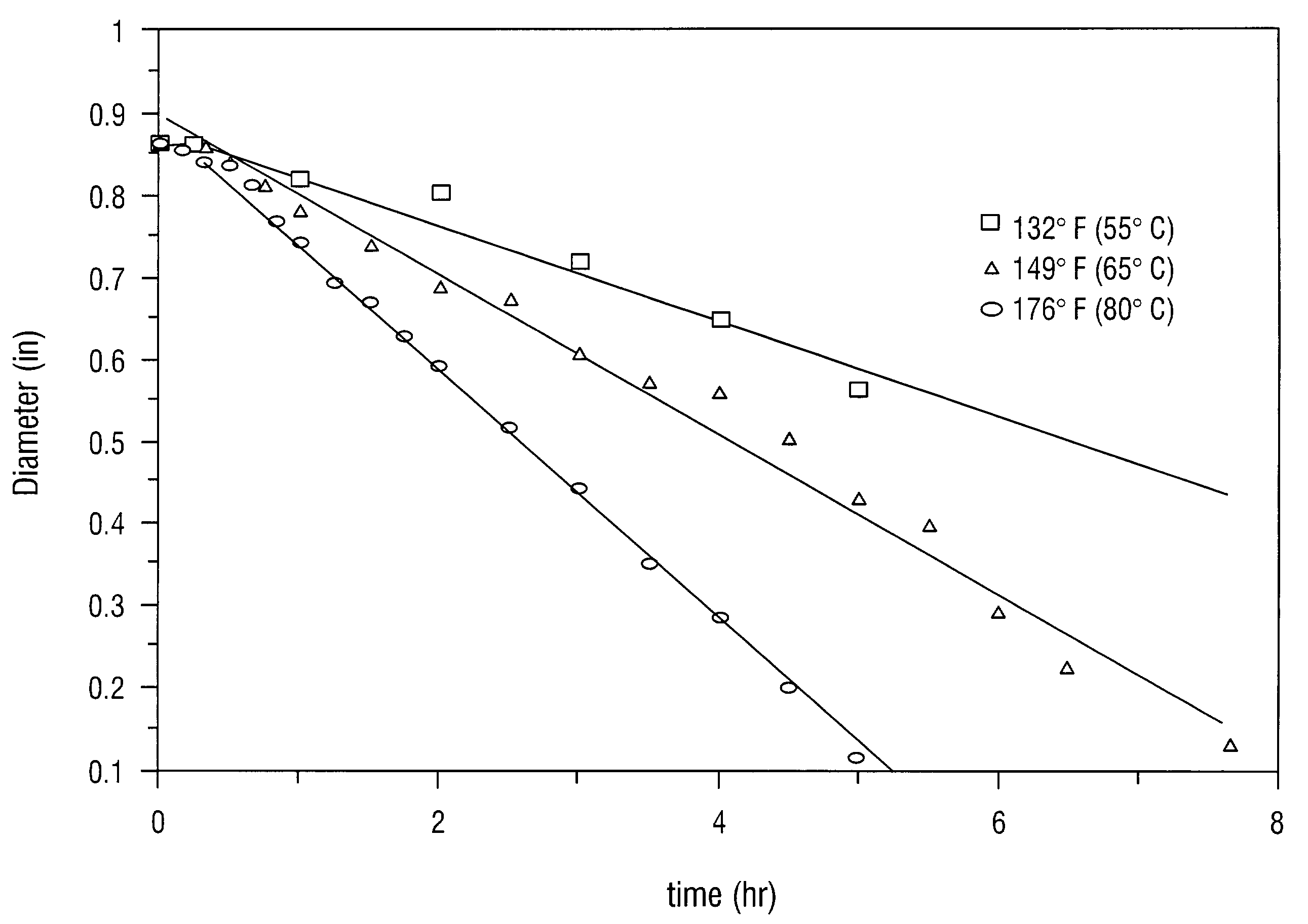
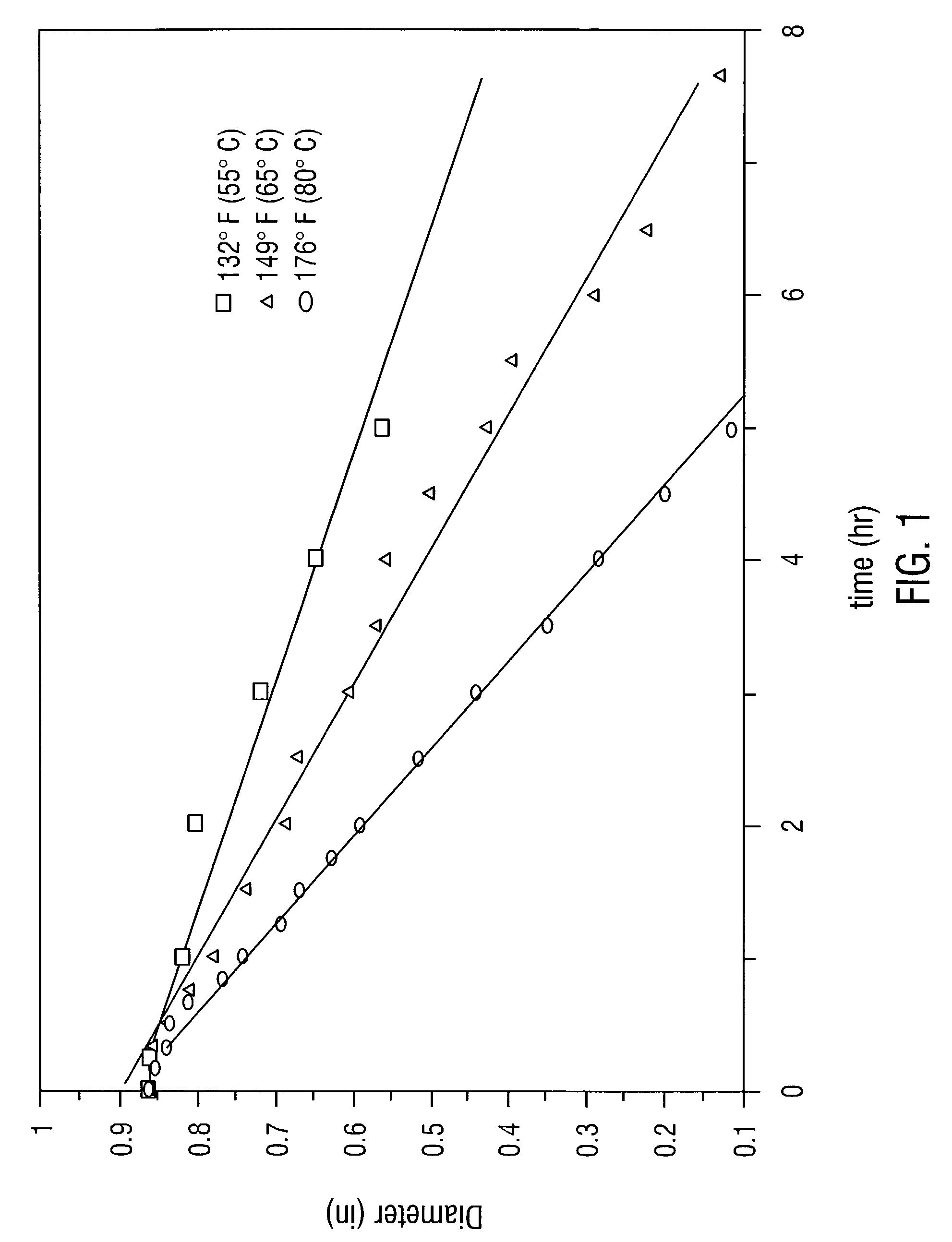
[0063]The material composition used is a polyvinyl alcohol copolymer under the trade name of BioBalls MR™ made from the hydrolysis of polyvinyl acetate. The molecular weight is 400,000 to 800,000 daltons and there is about 88% hydrolysis of the polyvinyl acetate. The copolymer has been formed into solid spheres of diameter less than one inch. FIG. 1 shows that as the temperature is increased, the solubility of the copolymer increases. Three different temperatures are shown to illustrate the effect of each temperature on the copolymer spheres.

example 2

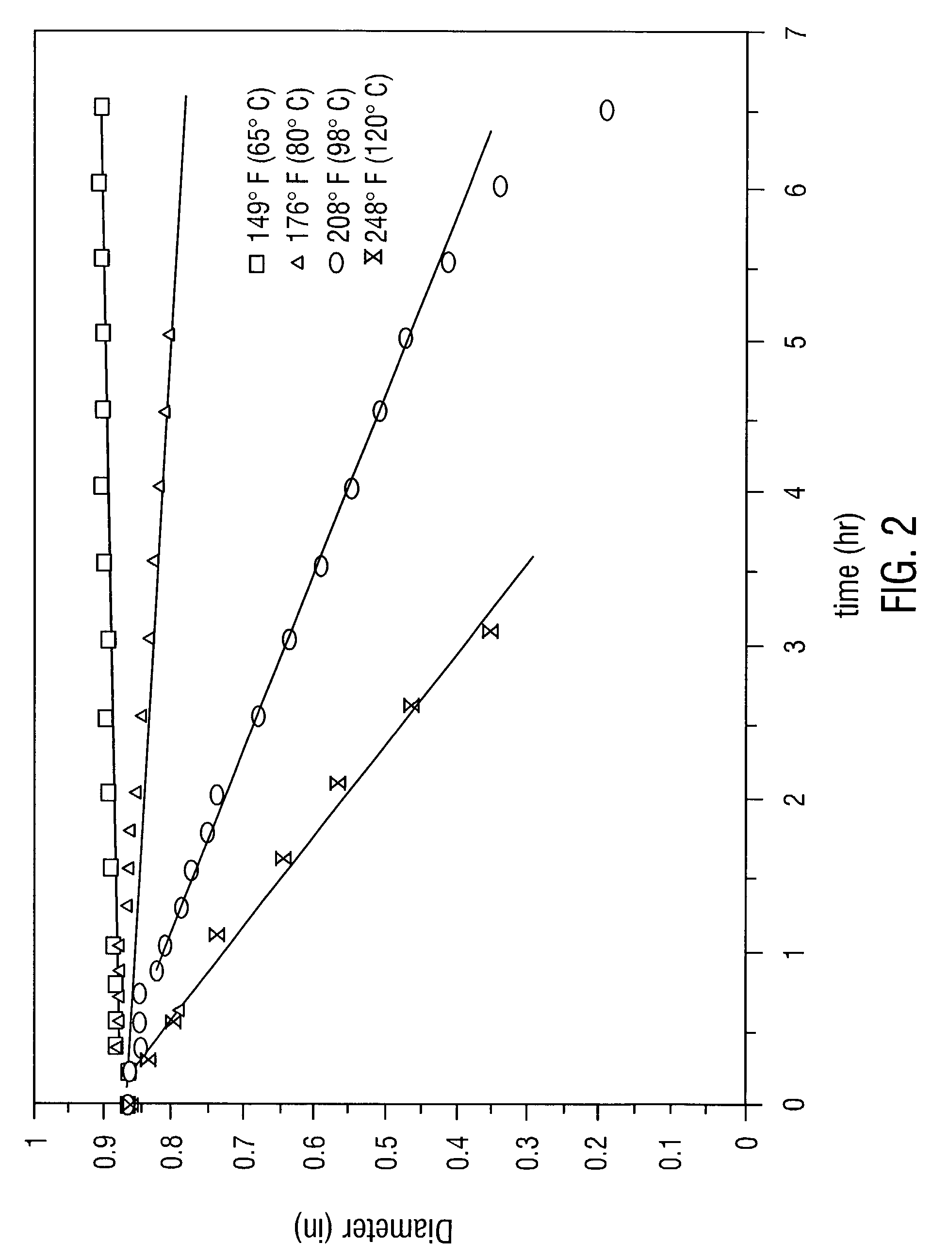
[0064]The material composition is a polyvinyl alcohol copolymer under the trade name of BioBalls HR™ made from the hydrolysis of polyvinyl acetate. The molecular weight is 400,000 to 800,000 daltons and there is about 95% hydrolysis of the polyvinyl acetate. The copolymer has been formed into solid spheres of diameter less than one inch. As the temperature is increased above 80° C., the polymer begins to dissolve. One of skill in the art will appreciate that solubility of the copolymer increases only after a certain temperature is reached. FIG. 2 shows the dissolution rates at 98° C. and 120° C.

[0065]In each of the above examples the material can be used to encapsulate a chemical that is required downhole. With a hollow spherical shape the inside could be filled with the chemical. The chemical may be admixed into the copolymer and then formed into a spherical or other desirable shapes.

[0066]To protect the shell until use, a wax or other type of coating could be used to line the insi...


PUM

PropertyMeasurementUnit
Timeaaaaaaaaaa
Timeaaaaaaaaaa
Thicknessaaaaaaaaaa

Abstract

The invention provides a method of treating of a well, a formation, or both, with the solids, liquids, or apparatuses, by 1) encasing said solids, liquids, or apparatuses in a water-soluble shell, 2) conveying said encased solids, liquids, or apparatuses to a predetermined location in the well, and then 3) allowing the water-soluble shell to dissolve in the aqueous phase in the wellbore. The shell is preferably made of water-soluble polyvinyl alcohol copolymers and a waterproofing agent. The shell encases a variety of solids, liquids, or combinations thereof, where said solids or liquids are useful in the treatment of the well or of the producing formation. Illustrative encased material includes soap, acid, corrosion inhibitors, chelating agents, scale inhibitors, mutual solvents, paraffin inhibitors, paraffin dissolvers, clay stabilizers, and tracer materials. The encased materials may also be apparatuses, such as a prefabricated screen completion or a prefabricated sand-pack. The tool used to deliver the apparatuses may also be made from a water-soluble polyvinyl alcohol copolymer.

Description

FIELD OF THE INVENTION[0001]The invention relates generally to a dissolvable encapsulating material, and to its use to convey materials, chemicals, and other devices down a wellbore.BACKGROUND OF THE INVENTION[0002]In the oils and gas industry there are producing wells which range from several hundred feet to over 20,000 feet in depth. These wells are narrow, often less than six inches in diameter. In addition, these wells typically have smaller diameter tubes suspended therein. It is often necessary to place chemicals or other apparatus at or near the bottom of the wellbore.[0003]In the case of fluids, the current methods of placing chemicals near or at the bottom of a wellbore are to either push a plug of the fluid down the well, displacing fluid in the wellbore, or to suspend a small diameter tube, often called a coiled tube, down the well, and push the fluid down this coiled tube. Both methods have substantial drawbacks. The chemical may absorb or react with components in the we...

Claims


Application Information

Patent Timeline
IPC IPC(8): C09K8/00C09K8/516C09K8/536C09K8/70
CPCC09K8/516C09K8/70C09K8/536Y10S507/902
Inventor SINCLAIR, A. RICHARDSMITH, S. BYRON
Owner TECHNISAND
Why Eureka
Try Eureka