Electromagnetic induction type position sensor

a position sensor and induction type technology, applied in the field of electromagnetic induction type position sensors, can solve the problems of reducing the detection accuracy, not being able to detect highly accurate positions, and using permanent magnets

Active Publication Date: 2006-05-23
OKUMA CORP
View PDF18 Cites 40 Cited by
  • Summary
  • Abstract
  • Description
  • Claims
  • Application Information

AI Technical Summary

Problems solved by technology

However, the position sensor using the magnetoresistive element disclosed in Japanese Patent Publication Laid-open No. 62-274215, which is widely used as the position sensor for the main shaft, is not suitable for highly accurate position detection because of unsatisfactory temperature characteristics of the magnetoresistive element.
Moreover, the use of the permanent magnet can be problematic in that iron powder produced, for example, by the machine work, tends to stick to sensor surfaces, where its presence reduces the accuracy of detection.
However, a problem with a sensor using a plurality of coils is that the unamplified output signal level is low, such that, if the indentation pitch of the scale is reduced for higher accuracy, the detectable signal level will be extremely low.
In addition, even with the reduced indentation pitch, detection resolution in the indentation pitch will decrease due to noise, so that it is difficult to increase the accuracy.
Furthermore, when, for example, printed circuit board technology is used to arrange the coils of the sinusoidal conductive patterns having a short wavelength, there is also a problem that an inwrought coil can not be implemented because for the footprint of an interlayer connection is several times larger than a conductor width (thickness of the conductive pattern).
This has caused a problem that the area of the coils receiving the magnetic flux is reduced, leading to reduced detected signal level.
Moreover, there is a problem that, although the inwrought coil can be implemented in the small indentation pitch, it is difficult to maintain the accuracy of the sinusoidal coil shape via a plurality of layers.
Thus, there is also a problem that, even if the detected signal level can be increased by the inwrought coil, highly accurate positional detection in the indentation pitch becomes possible due to degraded coil shape accuracy.
In addition, as in Japanese Patent Publication Laid-open No. 8-313295, use is made of a coil in which two sinusoidal conductive patterns having a large amplitude in reverse phases are connected in series so as to perform highly accurate positional detection, in which case a coil and a scale are needed which generate an AC magnetic flux that is sufficiently great for the amplitude of the sinusoidal conductive patterns, resulting in a problem that the size of the position sensor is increased.
Also, when the scale is small in a thickness direction, a portion of the sinusoidal conductive pattern is disposed at a location where the magnetic flux proximate to a scale edge rapidly changes, thus posing the same problem.

Method used


Image

  • Electromagnetic induction type position sensor
  • Electromagnetic induction type position sensor
  • Electromagnetic induction type position sensor

Examples


second embodiment

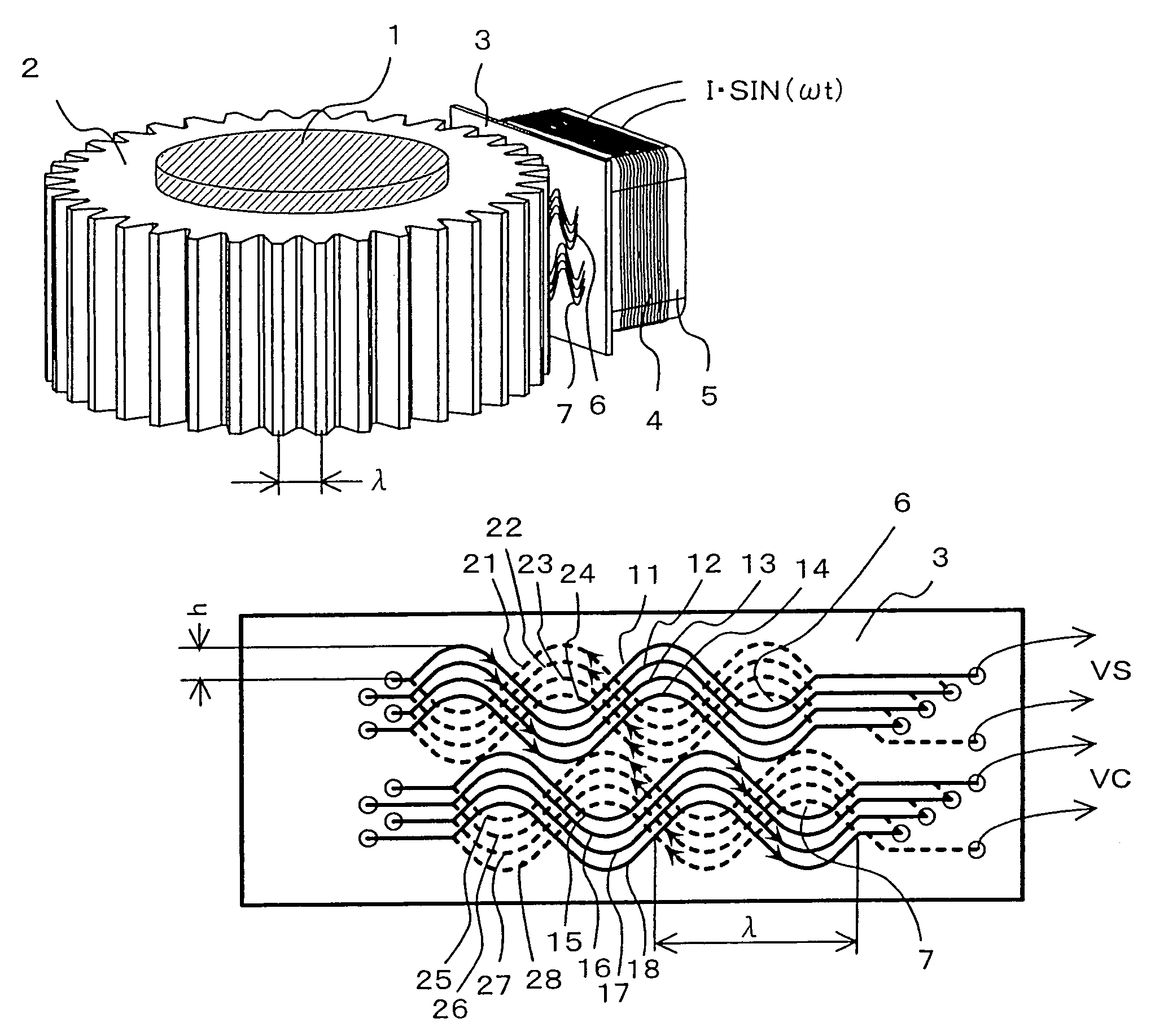
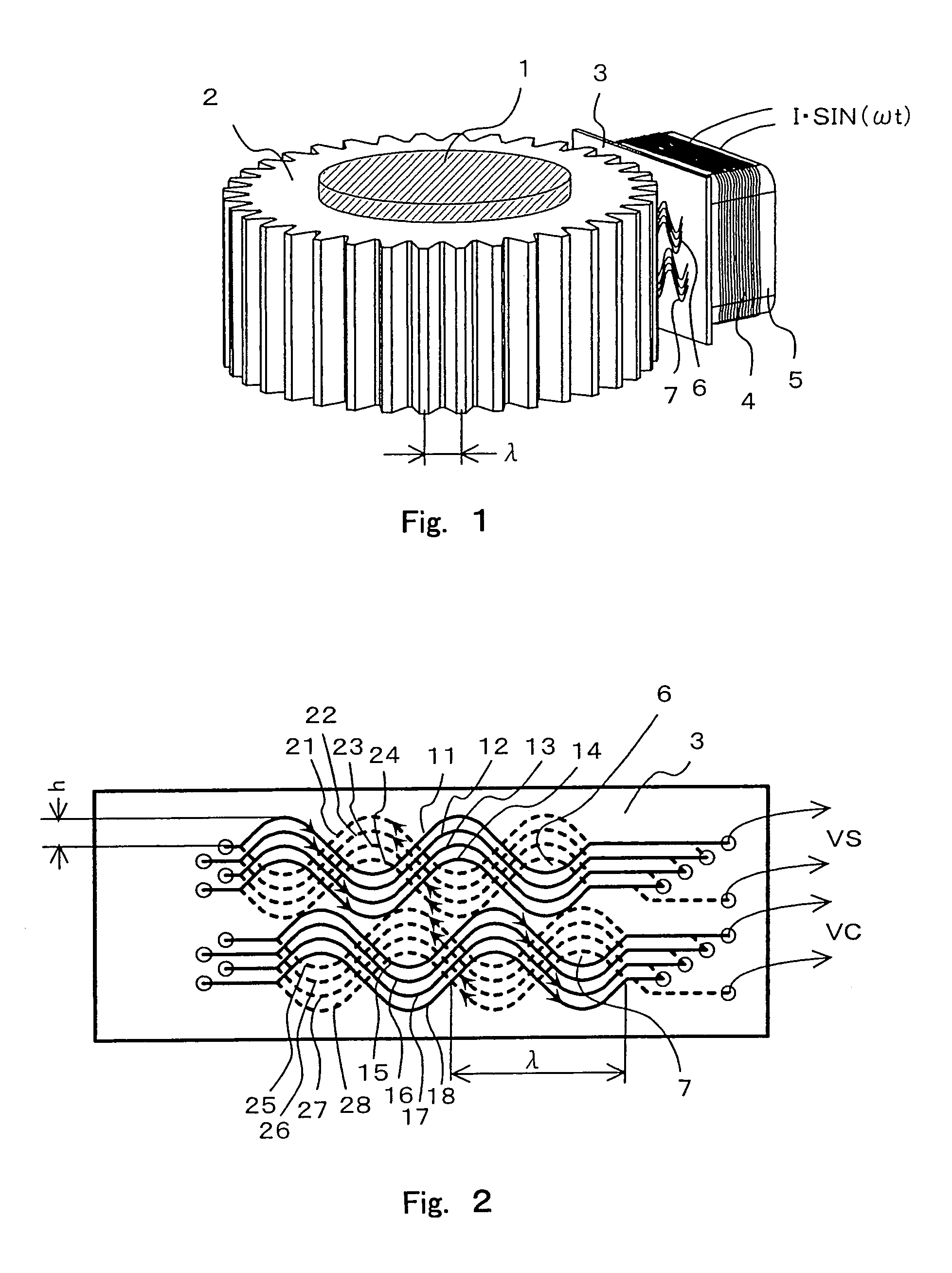
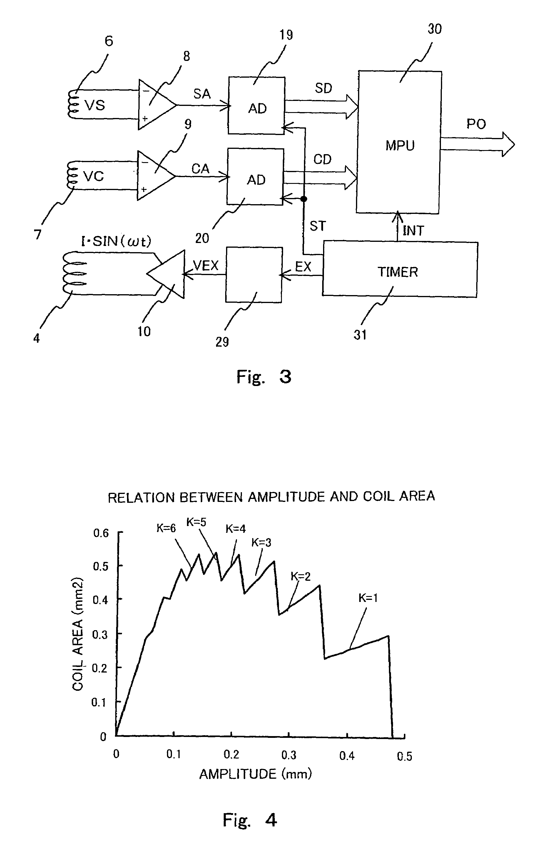
[0031]FIG. 5 is a diagram showing a sensor substrate according to a In a sensor substrate 40 of FIG. 5, there are arranged at regular intervals sinusoidal conductive pattern groups 32, 33, 34, 35 in which one group is composed of two pairs of conductive patterns corresponding to K=2 in the graph of FIG. 4. Further, the sinusoidal conductive pattern groups 32, 33 are connected in series to the sinusoidal conductive pattern groups 34, 35, respectively, thus forming two coils 61, 62. Thus, in the sensor substrate 40, centers of gravity of the coils 61, 62 can be located closer than those of the coils 6, 7 in FIG. 2. The closely located centers of gravity of the two coils makes it possible to restrict a decrease in position detection accuracy due to changes in signal amplitude balance and phase difference between the two signals VS and VC even if the sensor substrate is inclined in various directions.

third embodiment

[0032]Next, a third embodiment will be explained. In a sensor substrate 50 of FIG. 6, there are arranged sinusoidal conductive pattern groups 36, 37, 38, 39 in which one group is composed of two adjacent pairs of conductive patterns corresponding to K=2 in the graph of FIG. 4. Further, the sinusoidal conductive pattern groups 36, 35 are connected in series to the sinusoidal conductive pattern groups 39, 37, respectively, thus forming two coils 63, 64. Thus, in the sensor substrate 50, centers of gravity of the coils 63, 64 can be located closer than those of the coils 61, 62 in FIG. 5. However, in the sensor substrate 50, the conductive patterns of the coil 63 are disposed largely in outer peripheral parts where the change in the magnetic flux distribution is relatively great, leading to a disadvantage that characteristics of the two coils tend to be unbalanced.

fourth embodiment

[0033]Next, a fourth embodiment will be explained. In a first layer and a second layer of a sensor substrate 60 of FIG. 7, there are arranged eight pairs of sinusoidal conductive patterns (41 and 51, 42 and 52, 43 and 53, 44 and 54, 45 and 55, 46 and 56, 47 and 57, 48 and 58) having the wavelength λ at regular intervals in a direction (sinusoidal wave amplitude direction) vertical to the movement direction of the scale so that they are sequentially shifted by a regular phase difference π / 4 (λ / 8).

[0034]When one set of patterns is composed of two pairs of sinusoidal conductive patterns adjacent in the sinusoidal wave amplitude direction, four sets are possible, which include a set consisting of the sinusoidal conductive patterns 41, 42, 51, 52; a set consisting of 43, 44, 53, 54, a set consisting of 45, 46, 55, 56; and a set consisting of 47, 48, 57, 58. Four sinusoidal conductive patterns are connected in series so that, when viewed from the front of the sensor substrate 60, it appea...


PUM

PropertyMeasurementUnit
widthaaaaaaaaaa
widthaaaaaaaaaa
electromagneticaaaaaaaaaa

Abstract

An electromagnetic induction type position sensor comprises an AC magnetic flux generating device which generates AC magnetic flux substantially at a wavelength λ, and a plurality of coils which receives the AC magnetic flux to output electromagnetic induction voltages. Each coil includes a plurality of sinusoidal conductive patterns at a wavelength λ formed in each of an even number of layers laminated via insulating materials. The plurality of conductive patterns formed in a same layer is arranged with a space between them in an amplitude direction of the sinusoidal shape, and is formed at the same position as a plurality of conductive patterns formed in another adjacent layer, and its amplitude is in a reverse phase to that of the plurality of conductive patterns formed in the other adjacent layer. All the conductive patterns constituting the same coil are connected in series so that a direction of an electric current of these conductive patterns is opposite to that of the conductive patterns in reverse phases when viewed from the front of the layers.

Description

PRIORITY INFORMATION[0001]This application claims priority to Japanese Patent Application No. 2004-194159, filed Jun. 30, 2004, which is incorporated herein by reference in its entirety.BACKGROUND OF THE INVENTION[0002]1. Field of the Invention[0003]The present invention relates to an electromagnetic induction type position sensor which detects the position of movable members using an electromagnetic induction function.[0004]2. Description of the Related Art[0005]Position sensors measuring magnetic properties to detect, for example, the position of a main shaft of a machine tool have heretofore been known. In a typical such position sensor, a scale, which is a cylinder made of a soft magnetic material whose outer periphery is indented, is fixed to a rotating shaft; any change in the reluctance of the scale outer periphery is converted into an electric signal; and a relative position is thereby detected. Because such a position sensor bases positional detection on magnetic properties...

Claims


Application Information

Patent Timeline
Patent Type & Authority Patents(United States)
IPC IPC(8): H01F5/00
CPCG01D5/2046H01F5/003
Inventor HAYASHI, YASUKAZUFUKUI, NORIYUKI
Owner OKUMA CORP
Why Eureka
Try Eureka