
High precision servo track writing with position error signal feedback

a position error and servo track technology, applied in the direction of data recording, magnetic recording, instruments, etc., can solve the problems of long servo writing time of servo writers, low-quality servo tracks written with the head, and low signal available for feedback, so as to achieve high bandwidth, high bandwidth, and high disk rpm

Inactive Publication Date: 2006-05-23
MAXTOR
View PDF4 Cites 12 Cited by
  • Summary
  • Abstract
  • Description
  • Claims
  • Application Information

AI Technical Summary

Benefits of technology

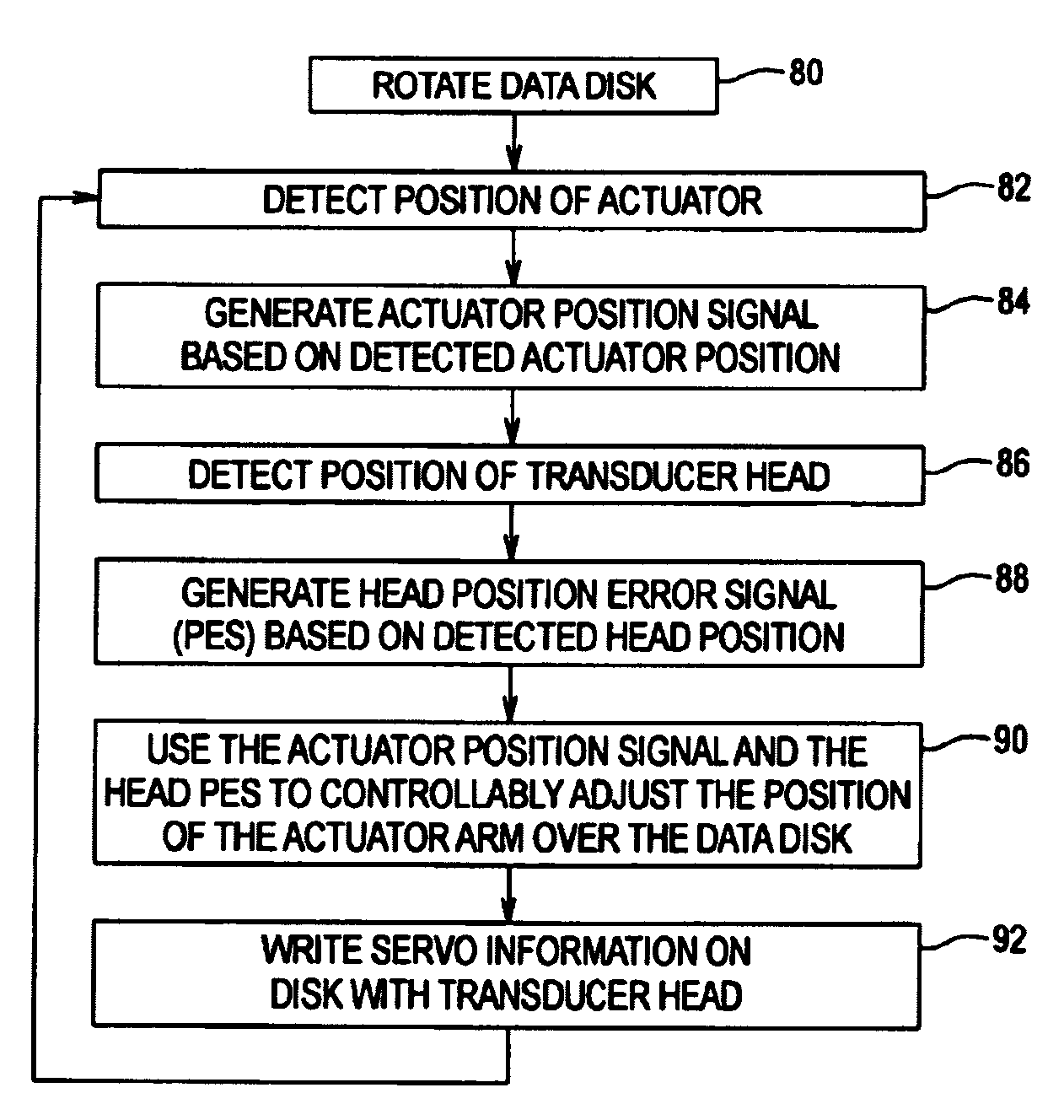
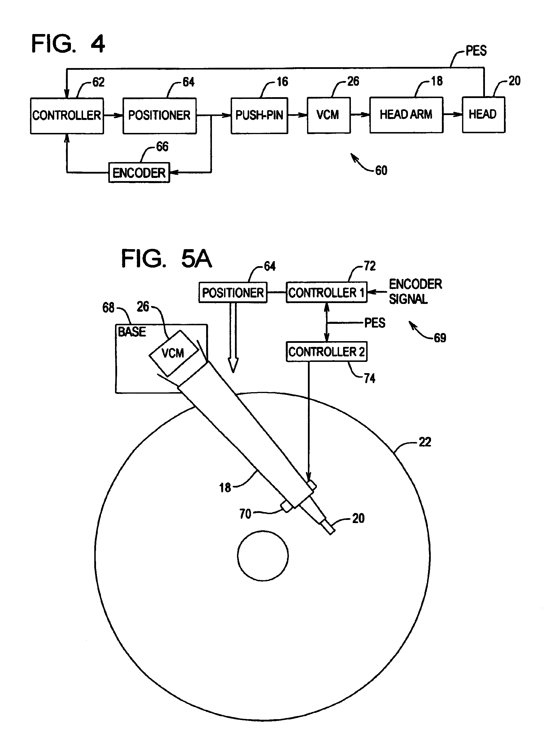
[0013]The present invention satisfies these needs. In one embodiment, the present invention uses the readers of the magnetic heads of a disk drive to read position information during servo writing of a data disk in the disk drive, using a servo track writer. A positioning system in the servo writer uses both actuator position information and said head position information as feedback signals, to more accurately position said head during servo writing, resulting in written servo tracks with improved quality.
[0015]As such, according to the present invention, head off-track is measured directly using the PES, and used as feedback along with actuator position in a servo writer servo loop for servoing during servo writing. Much higher sampling rates allow the servo writer servo loop to have high bandwidth. Position errors due to written in run out are no larger than the drive non-repeatable PES. Because the servo loop is closed around the PES during servo writing, much higher disk RPM may be used to take advantage of the high bandwidth servo loop. As a result, servo writing time can be reduced as well.

Problems solved by technology

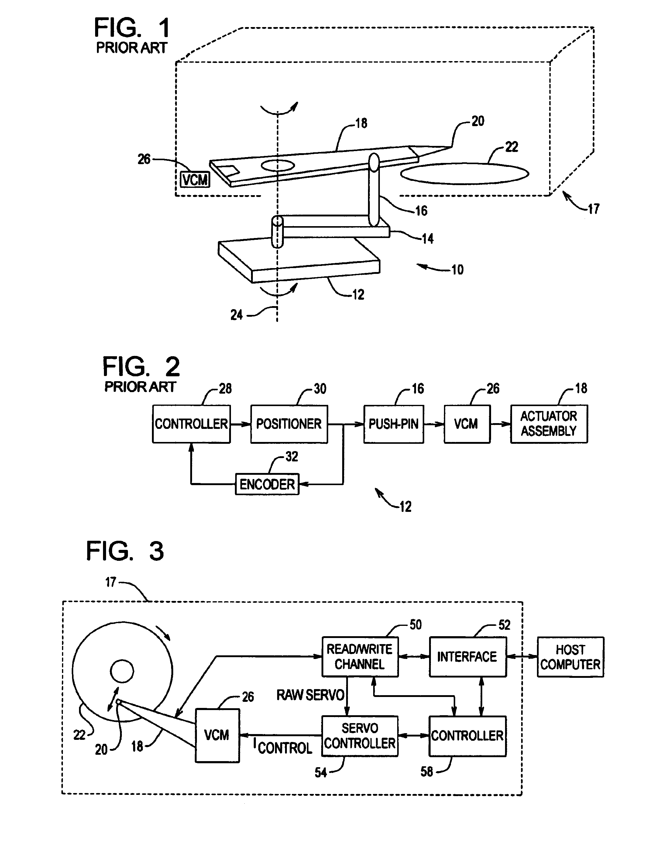
However, a disadvantage of above control schemes is that the only feedback position signal available is the rotational position of the push-pin via the encoder 32.
As such, corrections to head position to compensate for vibrations and head off-track position cannot be made, resulting in writing low quality servo tracks with the head, which may have to be re-written.
Another disadvantage of conventional servo writers is the lengthy servo writing time.
Thus, servo writing using conventional servo writers requires time penalties in the manufacturing process attributable to servo writer bottleneck.

Method used


Image

  • High precision servo track writing with position error signal feedback
  • High precision servo track writing with position error signal feedback
  • High precision servo track writing with position error signal feedback

Examples


Embodiment Construction

[0028]FIG. 3 shows a block diagram illustrating an example disk drive 17 that can be servo written, according to the present invention. Once servo written, the disk drive 17 can be coupled to an external host computer that uses the disk drive 17 as a mass storage device. It should be appreciated that the blocks illustrated in FIG. 3 are functional in nature and do not necessarily represent discrete hardware elements. For example, in one approach, two or more of the functional blocks within the disk drive 17 are implemented in software in a common digital processor. The disk drive 17 includes at least one data storage disk 22, at least one transducer head 20, an actuator arm assembly 18, a voice coil motor (VCM) 26, a read / write channel 50, an interface unit 52, a servo controller 54 and a disk drive controller 58.

[0029]In a preferred embodiment, the disk drive 17 includes multiple disks 22 in a vertical stack arrangement with one transducer 20 for each operative disk surface. Typica...


PUM


Abstract

A servo writer system for a disk drive uses the reader element of a magnetic transducer head in the disk drive to read head position information during servo writing of the disk drive. A positioning system in the servo writer uses both the head position information and actuator position information, as feedback signals to accurately position the transducer during servo writing, resulting in high quality servo tracks.

Description

RELATED APPLICATIONS[0001]Applicant claims the priority of U.S. Provisional Application No. 60 / 285,056, entitled “High Precision Servo Track Writing with Position Error Signal Feedback”, filed on Apr. 19, 2001, which is incorporated herein by reference.FIELD OF THE INVENTION[0002]The present invention relates to data storage in data disk drives, and more particularly to servo writing of data disk drives.BACKGROUND OF THE INVENTION[0003]Disk drives are well known in the computer art for providing secondary mass storage with random access. A disk drive essentially comprises one or more magnetic data storage disks rotating on a spindle by a spindle motor, within an enclosed housing. A magnetic transducer head is placed on an actuator arm and positioned very closely to each data storage surface by a slider suspended upon an air bearing. Servo information are typically written in servo sectors which interrupt data sectors or blocks on each disk. Servo information provide a servo control ...

Claims


Application Information

Patent Timeline
IPC IPC(8): G11B21/02G11B5/596
CPCG11B5/59633
Inventor GUO, LINTUNG, DAVIDKHONG, HENG-POH
Owner MAXTOR
Learn More