Roll-up pool for a decontamination system

a decontamination system and roll-up technology, applied in the field of decontamination systems, can solve the problems of contamination of personnel in the vicinity, contamination of personnel during industrial accidents, and containment of run-off water, so as to reduce the likelihood of recontamination, reduce the time required, and facilitate storage

Inactive Publication Date: 2006-05-30
VANBASTEN WILLEM F
View PDF6 Cites 8 Cited by
  • Summary
  • Abstract
  • Description
  • Claims
  • Application Information

AI Technical Summary

Benefits of technology

[0013]The invention may also include fasteners, or other means for connecting a shower curtain, used as part of a temporary shower stall, to the roll-up pool. In this way, the invention prevents water from the shower from exiting the shower stall when the device is used outside in windy conditions.
[0023]The invention has the further object of providing a method of rapidly setting up a decontamination pool for emergency or other use.

Problems solved by technology

Personnel may become contaminated during industrial accidents, such as leaks in chemical plants, or by spillage of hazardous substances as a result of railroad or highway accidents.
Leakage of radiation from a nuclear reactor can also cause contamination of personnel in the vicinity.
A major problem with the procedure described above is the containment of run-off water.
It is therefore not advisable for a user to stand directly in the contaminated water.
If the temporary shower stall includes a shower curtain, and the unit is installed outside, water may escape the stall when the curtain is fluttering in windy conditions.
Also, containment of water is made more difficult when the temporary shower stall is assembled on sloping terrain, because water tends to overflow from the low end of the stall.
While the above-described solution ameliorates the problem of how to handle the contaminated run-off water, it has substantial disadvantages.
Moreover, when the pool fills with water, the grid sections may begin to float, causing a hazard to the users.
Most importantly, the grid requires time to assemble.
The need to deploy grids as described above substantially slows the process of assembling the decontamination unit.

Method used


Image

  • Roll-up pool for a decontamination system
  • Roll-up pool for a decontamination system
  • Roll-up pool for a decontamination system

Examples


Embodiment Construction

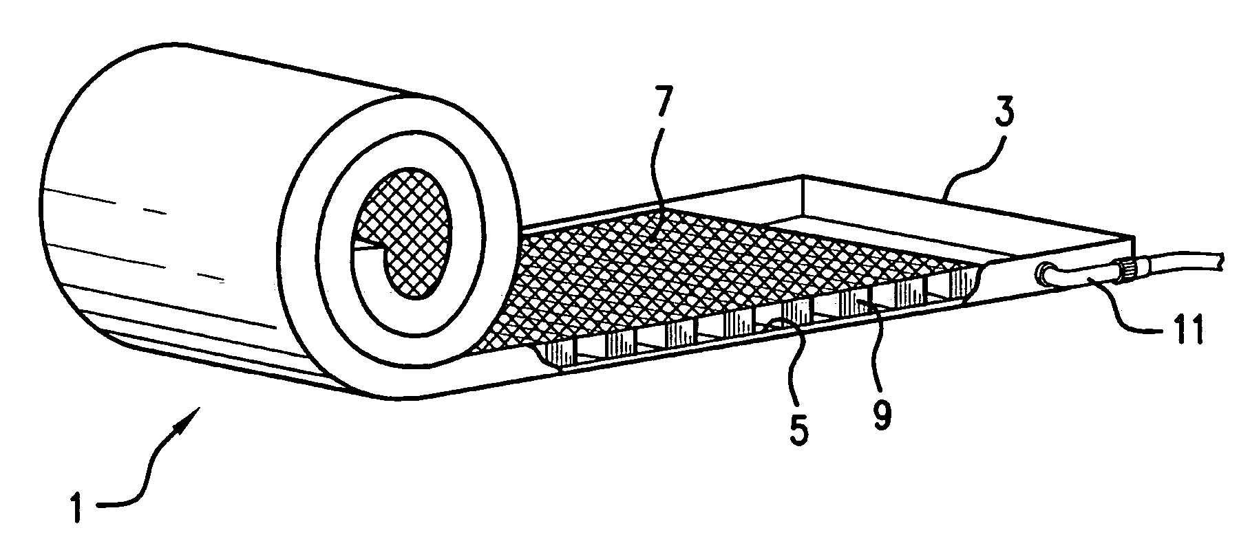
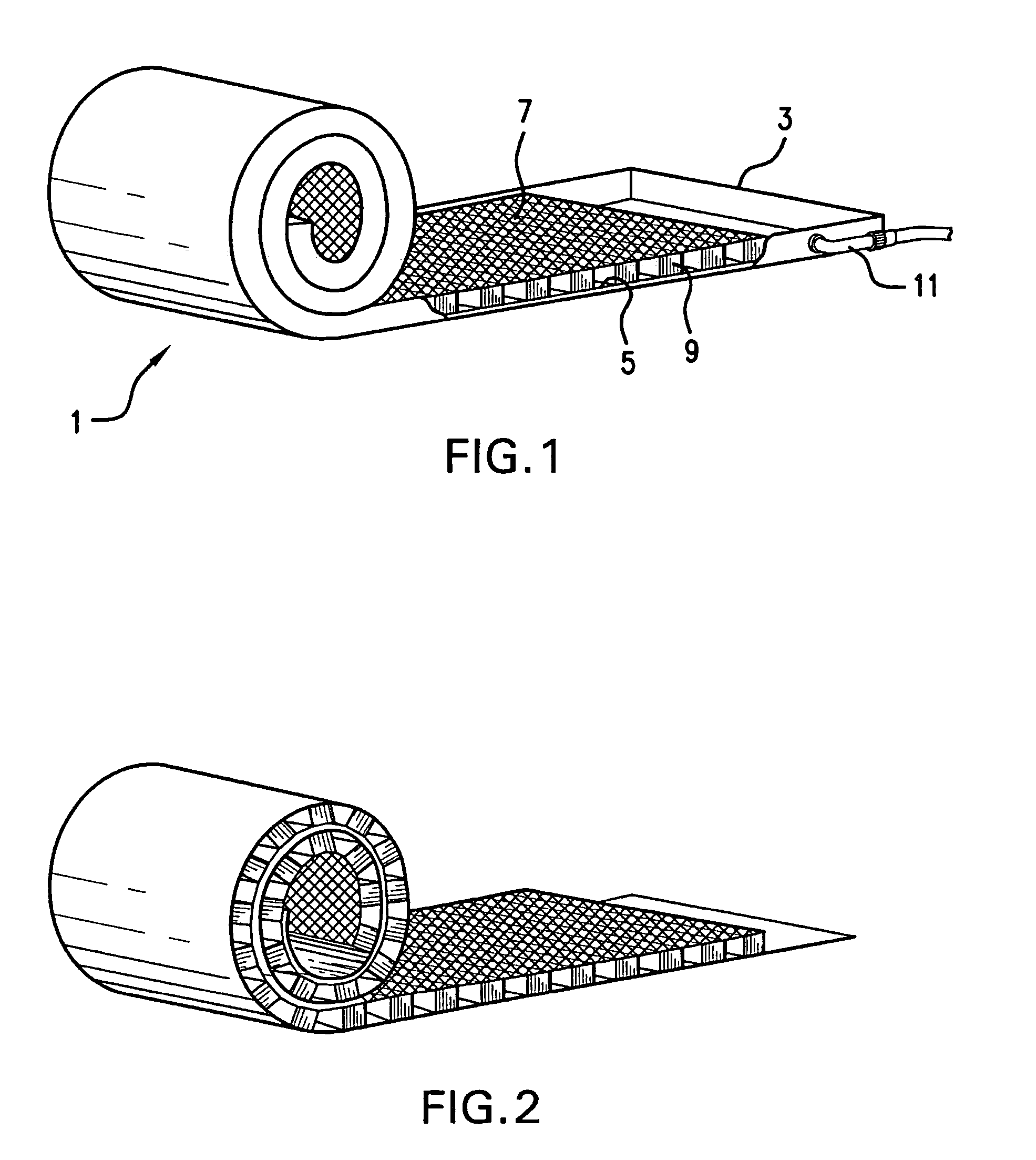
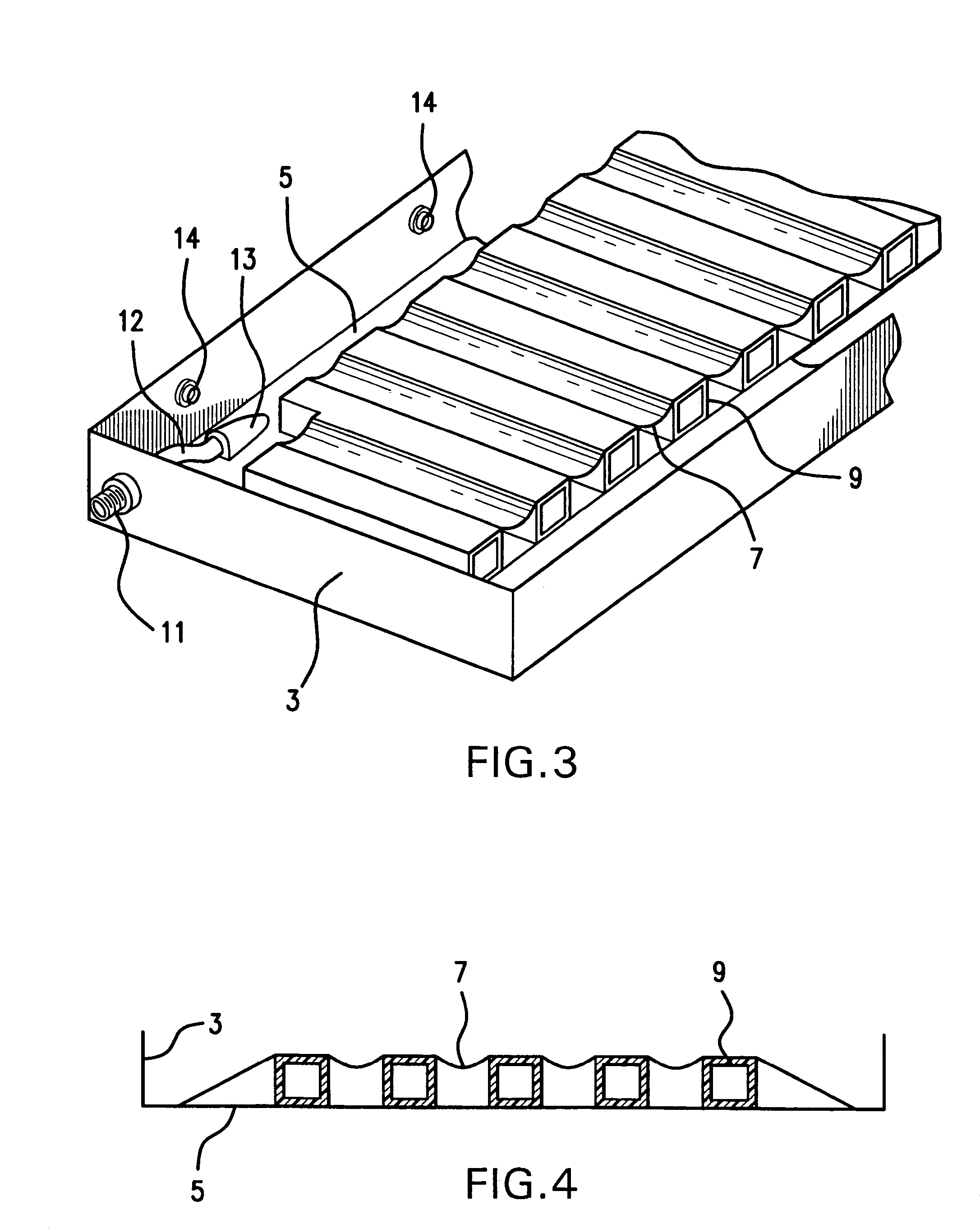
[0032]FIG. 1 provides a perspective view of a preferred embodiment of the present invention. FIGS. 3 and 4 provide additional details. FIG. 1 shows roll-up pool 1 in a partially rolled-up and partially unwound condition. The pool 1 is defined by bottom portion 5, preferably made of heavy-duty reinforced vinyl, or a stiff fabric, and by pool wall 3 which is also preferably made of the same material used to form the bottom portion, and which is welded to the bottom. The invention is not limited, however, by the specific choice of materials for the pool wall and floor, or by the means of assembly of the components. It is desirable that the pool wall and floor be sufficiently stiff and heavy that it can maintain its function of containing run-off water, but sufficiently flexible that it can be wound into a roll as shown in the figure.

[0033]The pool further includes an elevated grid or deck 7 which is supported by a plurality of elevation pieces 9. The deck 7 may be a solid piece of mate...


PUM


Abstract

A roll-up pool combines a collection basin and an elevation grid system into one unit that can be set up for use in seconds. The roll-up pool includes a bottom portion and wall portions, as well as an upper surface. A set of elevation pieces are located between the upper surface and the bottom portion, and are bonded to these components. All of these components are made of a material which is sufficiently flexible to allow the structure to be wound into a roll. When decontamination is required, the roll is unwound to provide a collection basin having an elevation grid system. In another embodiment, the rolled structure includes only the elevation grid system, and is intended for deployment in a collection basin that already exists. The invention substantially reduces the time and effort required to decontaminate victims of industrial accidents or chemical or biological attack.

Description

CROSS-REFERENCE TO PRIOR APPLICATION[0001]Priority is claimed from U.S. provisional patent application Ser. No. 60 / 451,729, filed Mar. 4, 2003, the disclosure of which is incorporated by reference herein.BACKGROUND OF THE INVENTION[0002]The present invention relates to the field of decontamination systems, and provides a portable, rapidly installable pool for collecting run-off water used in a decontamination system.[0003]The need for decontamination arises in many contexts. Personnel may become contaminated during industrial accidents, such as leaks in chemical plants, or by spillage of hazardous substances as a result of railroad or highway accidents. Leakage of radiation from a nuclear reactor can also cause contamination of personnel in the vicinity. More recently, the threat of chemical and biological attacks has highlighted the need for immediate decontamination of personnel that may come into contact with harmful substances such as bacteria, viruses, or chemical agents.[0004]...

Claims


Application Information

Patent Timeline
Patent Type & Authority Patents(United States)
IPC IPC(8): A47K3/062A61M1/00
CPCG21F9/22Y10T137/0402Y10T137/5762
Inventor VANBASTEN, WILLEM F.
Owner VANBASTEN WILLEM F
Why Eureka
Try Eureka