Multiphase mixing device with staged gas introduction

Inactive Publication Date: 2006-05-30
EXXON RES & ENG CO
View PDF20 Cites 43 Cited by
  • Summary
  • Abstract
  • Description
  • Claims
  • Application Information

AI Technical Summary

Benefits of technology

[0016]The present invention provides a novel means to provide more effective mixing of quench gas and process fluids in a height constrained interbed space whi

Problems solved by technology

First, the quench zone fails to erase lateral temperature differences at the outlet of the preceding bed or, in the worst cases, amplifies them.
The second sign of poor performance is that inlet temperature differences following the quench zone increase as the rate of quench gas is raised.
This indicates inadequate mixing of cooler gas with the hot process fluids.
Poor quench zone performance limits reactor operation in various ways.
When interbed mixing is unable to erase temperature differences, these persist or grow as the process fluids move down the reactor.
Hot spots in any bed lead to rapid deactivation of the catalyst in that region which shortens the total reactor cycle length.
Product selectivities are typically poorer at higher temperatures; hot regions can cause color, viscosity and other qualities to be off-specification.
), the exothermic reactions may become self-accelerating leading to a runaway which can damage the catalyst, the vessel, or downstream equipment.
Cognizant of these hazards, refiners operating with poor internal hardware must sacrifice yield or throughput to avoid these temperature limitations.
The trend to hi

Method used


Image

  • Multiphase mixing device with staged gas introduction
  • Multiphase mixing device with staged gas introduction
  • Multiphase mixing device with staged gas introduction

Examples


first embodiment

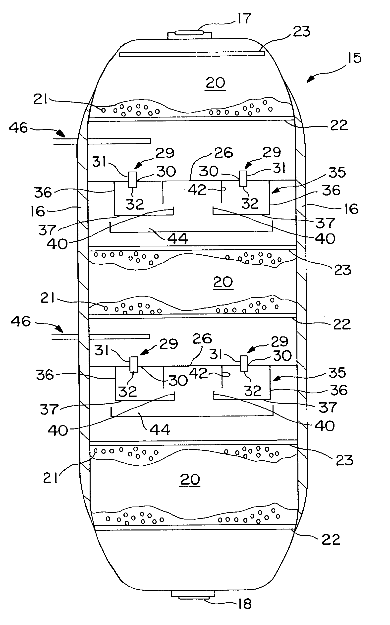
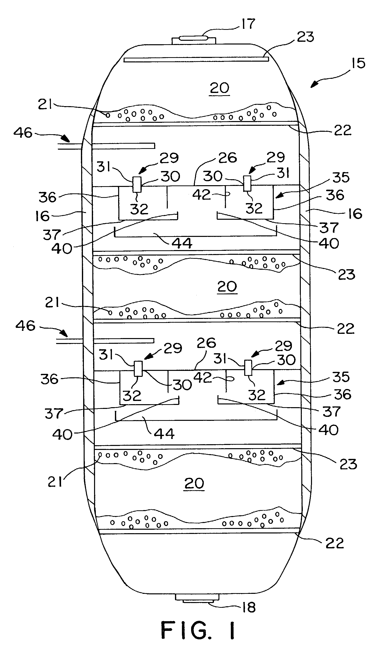
[0026]FIG. 1 shows, in simplified form, a hydroprocessing reactor column in accordance with the present invention. FIG. 1, FIG. 2, and FIG. 3 taken together, illustrate the present invention thereof. The general configuration of the reactor is conventional, as are details such as the supports for the grids and distributor plates, which are not shown for purposes of clarity. The reactor column 15 is formed as a generally cylindrical chamber having an outer wall 16. A reactor inlet 17 and a reactor outlet 18 are provided for introducing and discharging fluids from the reactor column 15. The reactor column 15 further comprises one or more catalyst beds 20 positioned along the longitudinal axis of the reactor column 15. Each of the catalyst beds 20 contains catalyst material 21, which is preferably supported below by a catalyst support grid 22. The catalyst support grid 22, together with the outer wall 16, provides direct support for the catalyst material 21. Alternatively, the catalys...

third embodiment

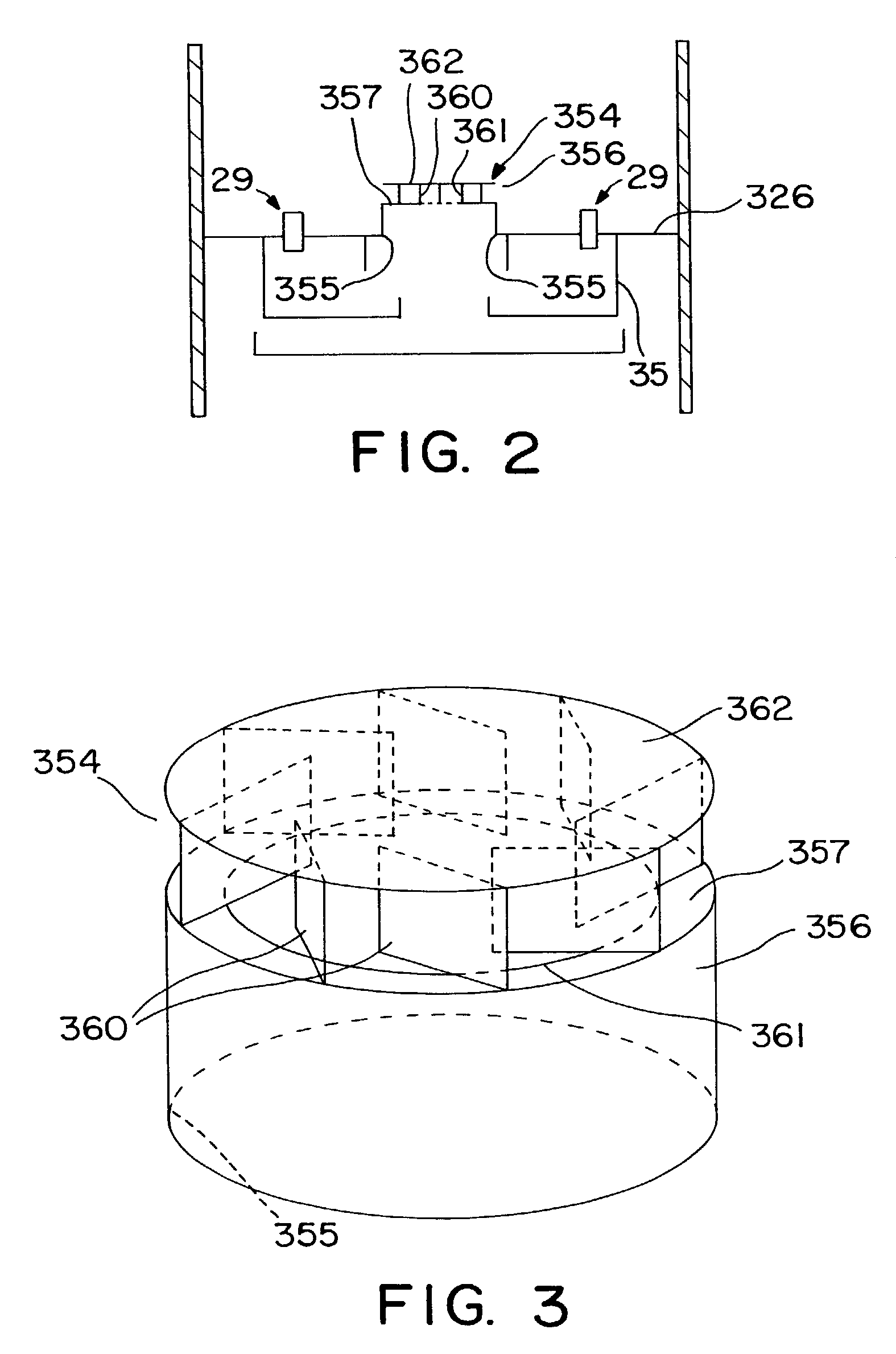
[0039]Turning now to FIG. 5, the present invention is next discussed. In this embodiment, the mixing system comprises an upwardly projecting sub-region or raised cap 354. As shown, the upwardly projecting sub-region 354 is formed over an opening 255 in the collection tray 126 as an upwardly extending wall 356 positioned above the perimeter of opening 255 such that wall 356 is coextensive with baffle 242 if baffle is present as shown in FIG. 5. If baffle 242 is not present, any opening size within the circumference formed by the passageways 29 may be used. The height of the upwardly extending wall 356 may be varied to suit the particular application for which the mixing system is to be used.

[0040]The mixing system in the third embodiment of the present invention comprises at least one and preferably a plurality of spillways 464 which direct a portion or slipstream of the vapor phase components of the product fluid, unreacted reactant fluid, quench fluids, and / or supplemental reactant...

fourth embodiment

[0041]In yet another embodiment of the mixing system of the present invention, which is illustrated by FIGS. 6 and 7, conduits are included such that they pass through the vertical wall of a raised cylindrical volume in the collection tray. In this fourth embodiment of the present invention, these conduits terminate in a tangential orientation to create beneficial rotational flow within the raised volume. In this embodiment, it is preferable that the cylindrical cap, which comprises upwardly projecting sub-region 554, extends even higher above collection tray 526 than the upwardly projecting sub-regions discussed in previously described embodiments.

[0042]The mixing system according to the fourth embodiment of the present invention comprises a plurality of inlets 566, which direct a portion or slipstream of the vapor phase components of the product fluid, unreacted reactant fluid, quench fluids, and / or supplemental reactants from the upper region of the interbed mixing zone to the lo...


PUM

PropertyMeasurementUnit
Flow rateaaaaaaaaaa

Abstract

The present invention comprises a mixing system that provides improved mixing of quench gas and process fluids in a height constrained interbed space while not increasing pressure drop. In particular, the device improves the effectiveness of an existing mixing volume in mixing the gas phase of two-phase systems. The mixing system includes a horizontal collection tray, a mixing chamber positioned below the collection tray, at least one passageway extending through the collection tray into the mixing chamber, and a vapor slipstream passageway extending through the collection tray into the mixing chamber for directing a vapor slipstream from above the collection tray into the mixing chamber. The mixing chamber and the collection tray define a two-phase mixing volume. The passageway conducts fluid containing at least some vapor from above the collection tray into the mixing chamber. The mixing chamber preferably includes at least one outlet opening for the downward passage of fluid. The vapor slipstream passageway, optionally, comprises a plurality of inlets arranged to impart rotational movement to the vapor phase at a location within the mixing chamber where the vapor phase has substantially expended the kinetic energy of its initial entry into the mixing chamber. As a result of providing at least one additional passageway for a vapor slipstream, and optionally, including one or more baffles as described above, significant re-acceleration of the vapor phase is achieved in the mixing chamber resulting in improvements in mixing efficiency of both the vapor and liquid phases.

Description

FIELD OF THE INVENTION[0001]The present invention relates generally to systems for mixing process gases and liquids and more specifically to interbed quench and mixing systems involving cocurrent downflow reactors using fixed hardware.BACKGROUND OF THE INVENTION[0002]Downward flow reactors are used by the chemical and refining industries in a variety of processes, such as hydrotreating, hydrofinishing and hydrocracking. A typical downward flow reactor has a cylindrical outer wall with a catalyst bed positioned within the reactor. The catalyst bed generally rests on a catalyst support grid positioned horizontally within the reactor and spanning the complete diameter of the reactor. The catalyst support grid, together with the outer wall, cooperates to retain the catalyst or other particulate material in place. A distribution tray is positioned horizontally within the reactor at a location above the catalyst bed for evenly distributing process fluids onto the catalyst. The catalyst su...

Claims


Application Information

Patent Timeline
IPC IPC(8): B01J10/00B01J8/02B01J8/04C10G49/00
CPCB01J8/0492C10G49/002B01J2208/00849
Inventor MCDOUGALD, NEIL K.BOYD, SHERRI L.MULDOWNEY, GREGORY P.
Owner EXXON RES & ENG CO
Why Eureka
Try Eureka