Method and device for cleaning welding torches

a welding torch and cleaning technology, applied in the direction of gas flame welding apparatus, weld torch cleaning, auxilary device, etc., can solve the problems of faster and more intense torch cleaning, external and internal areas that can be cleaned with such tools,

Inactive Publication Date: 2006-05-30
VON DER OHE JUERGEN
View PDF10 Cites 4 Cited by
  • Summary
  • Abstract
  • Description
  • Claims
  • Application Information

AI Technical Summary

Benefits of technology

[0012]The advantage of this invention is that using the cold jet technology, in particular the employment of a mixture of CO2 pellets with air, the torches can be cleaned whatever their sizes or shapes are. The CO2 pellets, or the carbon dioxide snow have an impact on limited areas and cause them to cool down and become brittle so as to loosen the dirt and the air stream carries away the loosened dirt from inside and outside the welding torch.
[0013]Another advantage of this invention is that by using a cold jet technology no direct contact is made with the welding torch which means that the welding torch's surface may not suffer any denudation or other damages.
[0014]An additional advantage of this invention is that several welding torches, being different in shape and size, may be cleaned in one single cleaning station.

Problems solved by technology

The disadvantage with such approach is that only the external area and part of the internal area can be cleaned by such kind of tools.
Also, the circular layout of the torch selected due to the necessary rotation of the tools proved disadvantageous as it is an obstacle to the required adaptation of the torch's shape for the actual seam or spot area layout.
Another disadvantage is that the originally smooth and mostly nickel-plated surface of the torch undergoes a denudation and becomes rough due to its mechanical processing, which in turn causes an even faster and more intense dirtying of the torch.

Method used


Image

  • Method and device for cleaning welding torches
  • Method and device for cleaning welding torches
  • Method and device for cleaning welding torches

Examples


example 1

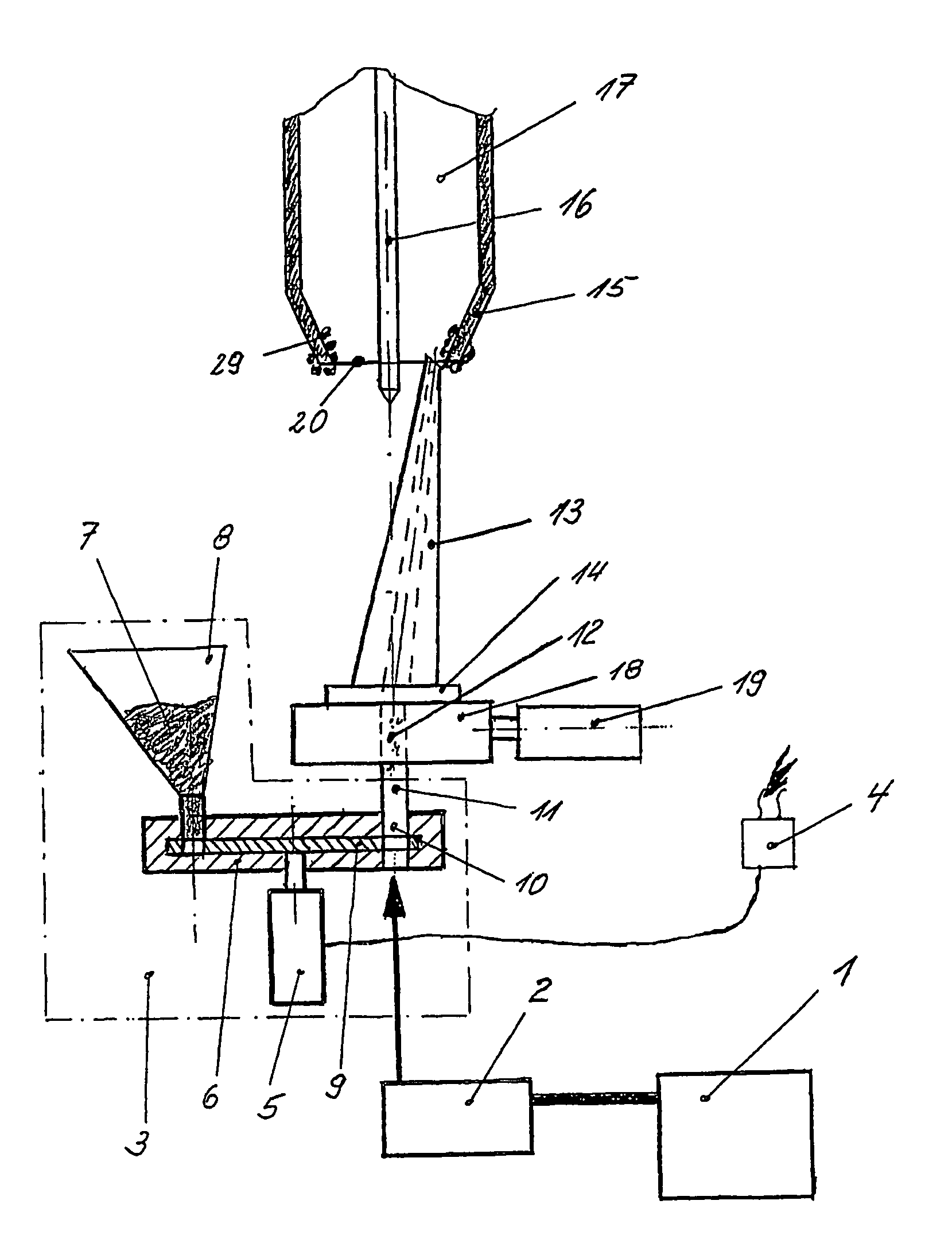
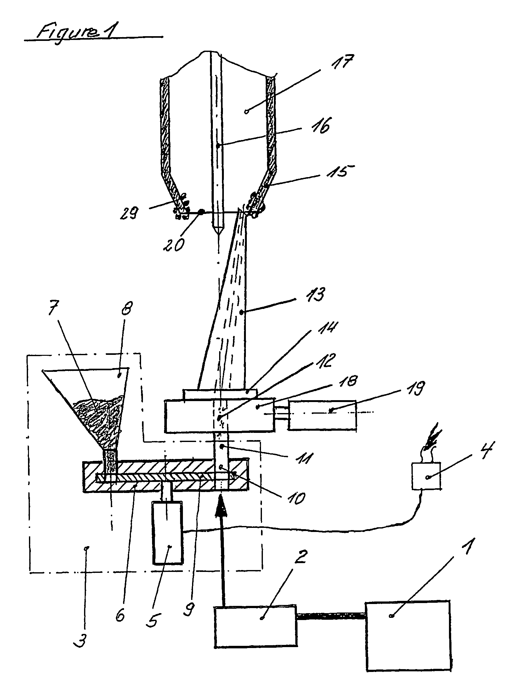
[0018]Compressed air supplied by a compressor (1) (not shown in detail) is heated and dried in the treatment station (2) and then guided to the jet cleaning station (3). A contact maker (4) is connected with the welding unit's working program. Approximately two seconds before end of the welding program, the contact maker (4) switches on the driving motor (5) of the proportioning device (6). From the storage bin (8), the CO2 pellets (7) run into the metering disc (9) and by turning the same reach the blasting station (10). In the blasting station (10), the CO2 pellets (7) are metered to the stream of compressed air fed in through the line (11). The stream of compressed air (12) enriched with CO2 pellets is guided to the jet nozzle (13). The jet nozzle (13) is fitted on an adapter (14) and, owing to the specific design of this adapter (14), is shifted out of its vertical position so that the stream of compressed air (12) is directed single-sided onto the area between the shielding gas...

example 2

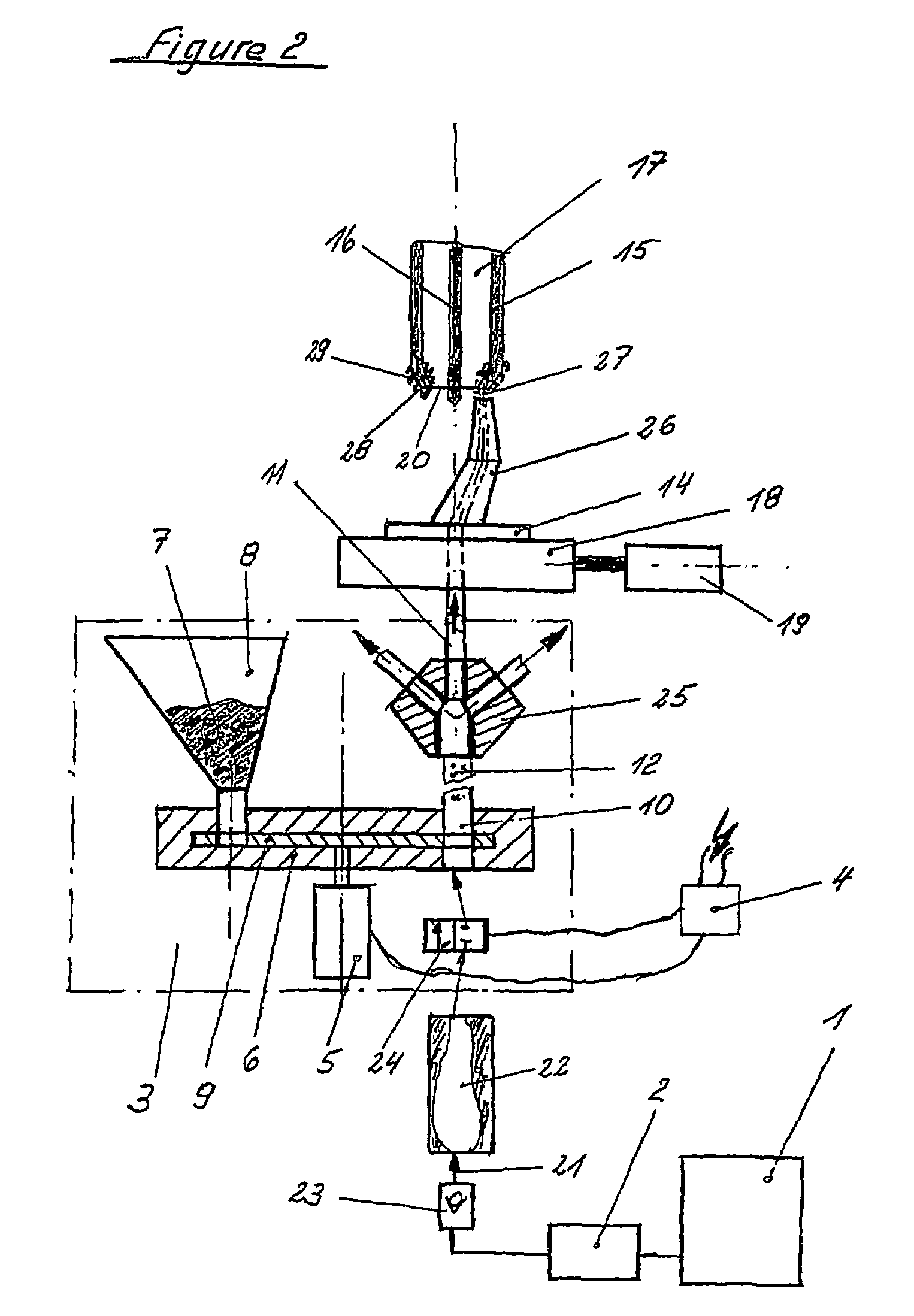
[0019]Compressed air supplied by the compressor (1) is heated and dried in the treatment station (2) and then fed through the line (21) into the storage capacity (22), which has the non-return valve (23) fitted upstream. Downstream, the storage capacity (22) is equipped with the valve (24) which is controlled by the contact maker (4). The driving motor (5) is triggered by the contact maker (4) and sets the metering disc (9) of the proportioning device (6) into a rotational motion. After a pre-selected time interval the valve (24) opens. In the blasting station (10), the outflowing compressed air is loaded with the CO2 pellets (7). The stream of compressed air (12) enriched with CO2 pellets is fed into a distributor (25), inside which the stream of compressed air (12) is apportioned in accordance with the number of angled jet nozzles (26) employed. The angled jet nozzles (26) are fitted on the adapter (14) where the rotary transmission (18) and the motor (19) set them into a rotation...


PUM

PropertyMeasurementUnit
areaaaaaaaaaaa
shapeaaaaaaaaaa
angleaaaaaaaaaa

Abstract

A method and a device for cleaning welding torches, for example in automated welding lines, on welding robots and in made-to-order production, by means of a cold medium, preferably CO2 dry ice. According to the method, a compressed air stream, charged with CO2 dry ice is directed constantly or at intervals by a jet nozzle onto one side of the surface to be cleaned and simultaneously describes a rotational movement.

Description

BACKGROUND OF THE INVENTION[0001]The invention relates to a method and a device for cleaning welding torches in automatic welding lines, on welding robots and hand-held devices used in fabrication of pieces tailored to specific needs.[0002]There are known several methods for cleaning welding torches. All these methods employ mechanical means of cleaning, using one or more wire brushes, several milling cutters or form cutters.[0003]The disadvantage with such approach is that only the external area and part of the internal area can be cleaned by such kind of tools. Smoke gas deposits are not removed completely from inside the torch, and neither are anti-stick agents that are blown in.[0004]Also, the circular layout of the torch selected due to the necessary rotation of the tools proved disadvantageous as it is an obstacle to the required adaptation of the torch's shape for the actual seam or spot area layout. Any modification in the torch's shape would entail a change of the cleaning ...

Claims


Application Information

Patent Timeline
Patent Type & Authority Patents(United States)
IPC IPC(8): B23K9/32B23K37/00B23K5/22B23K7/10B24C1/00B24C3/04
CPCB23K5/22B23K7/10B24C3/04B23K9/328B24C1/003B23K9/32
Inventor VON DER OHE, JUERGEN
Owner VON DER OHE JUERGEN
Why Eureka
Try Eureka