Charged particle therapy system, range modulation wheel device, and method of installing range modulation wheel device

a technology of charge particle therapy, which is applied in the direction of mass spectrometers, nuclear engineering, stability-of-path spectrometers, etc., can solve the problems of difficult operation, high time-consuming and labor-intensive installation of rmw to irradiation field forming apparatus, etc., and achieve the effect of increasing the number of patients treated and reducing the time required for treatmen

Inactive Publication Date: 2006-05-30
HITACHI LTD
View PDF1 Cites 208 Cited by
  • Summary
  • Abstract
  • Description
  • Claims
  • Application Information

AI Technical Summary

Benefits of technology

[0011]With the first aspect of the present invention, the range modulation wheel device has the housing, and the housing can be placed in contact with a component of the charged particle beam irradiation apparatus. Therefore, positioning of the rotary shaft of the range modulation wheel to a predetermined position can be performed in a short time. This contributes to cutting a time required for treatment per patient and increasing the number of patients treated.
[0013]Because the range modulation wheel device has the housing, the second aspect of the present invention can also provide the same advantages as those obtained with the first aspect of the present invention.
[0015]Because the range modulation wheel device has the housing, the third aspect of the present invention can also provide the same advantages as those obtained with the first aspect of the present invention.
[0016]According to the present invention, it is possible to cut a time required for treatment and to increase the number of patients treated.

Problems solved by technology

However, such an alignment operation is very difficult to carry out and installation of the RMW to the irradiation field forming apparatus takes a lot of time.

Method used


Image

  • Charged particle therapy system, range modulation wheel device, and method of installing range modulation wheel device
  • Charged particle therapy system, range modulation wheel device, and method of installing range modulation wheel device
  • Charged particle therapy system, range modulation wheel device, and method of installing range modulation wheel device

Examples


first embodiment

[First Embodiment]

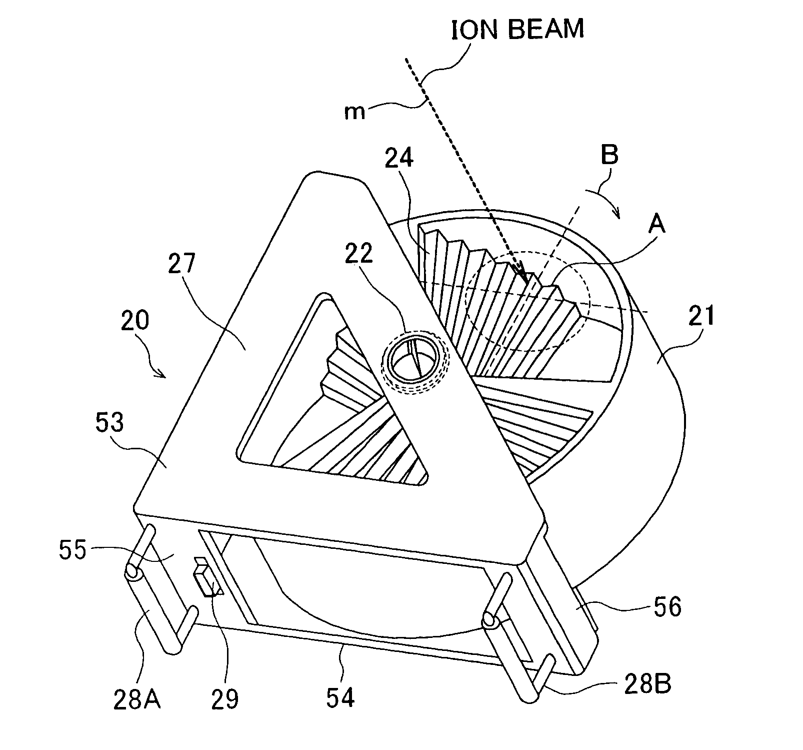
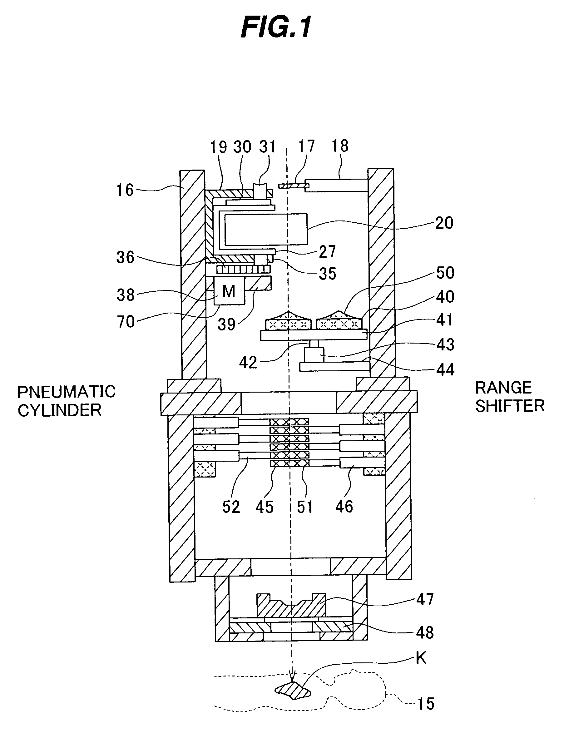
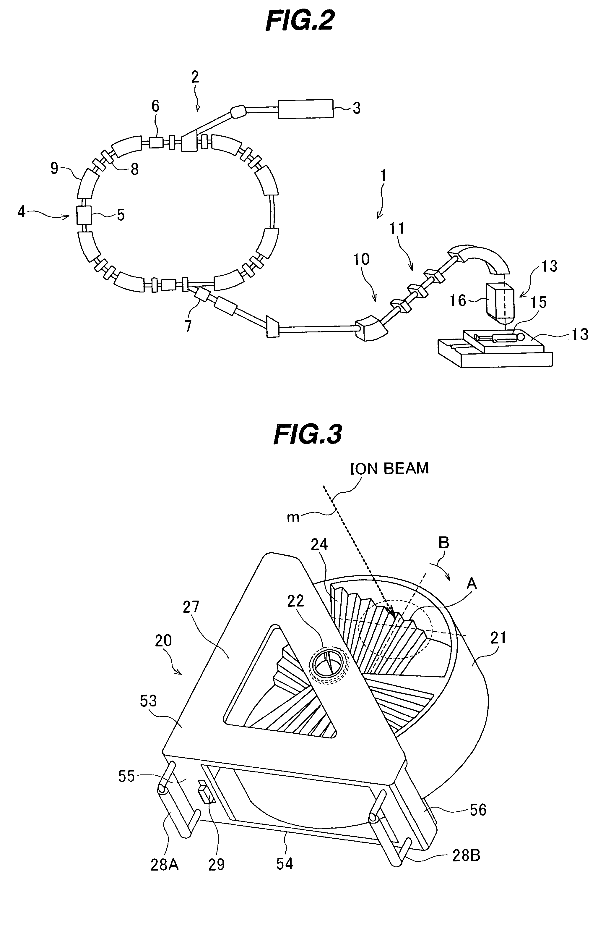
[0027]A charged particle therapy system representing a first preferred embodiment of the present invention will be described with reference to FIG. 2. A charged particle therapy system 1 of this embodiment comprises a charged particle beam generator 2 and an irradiation field forming apparatus (charged particle beam irradiation apparatus) 13. The charged particle beam generator 2 comprises an ion source (not shown), a pre-accelerator 3, and a synchrotron 4. Ions (e.g., protons (or carbon ions)) generated by the ion source are accelerated by the pre-accelerator (e.g., a linear accelerator) 3. An ion beam (charged particle beam) emitted from the pre-accelerator 3 enters the synchrotron 4. The ion beam is accelerated in the synchrotron 4 in which it is given with energy by radio-frequency (RF) power applied from an RF-accelerating cavity 5. After energy of the ion beam circulating in the synchrotron 4 has been increased up to a setting level, an RF wave is applied to ...

second embodiment

[Second Embodiment]

[0047]A charged particle therapy system according to a second embodiment of the present invention will be described below. The charged particle therapy system of this second embodiment differs only in the structure of the RMW device from the charged particle therapy system 1 of the above-described first embodiment. In other words, the charged particle therapy system of this embodiment has the same structure as that of the charged particle therapy system 1 except for the RMW device. As shown in FIG. 9, an RMW device 20A used in this embodiment has a joint member 60 in the form of a flat plate, which corresponds to the joint member 55, etc. of the RMW device 20. The joint member 60 couples a pair of housing members 64 to each other. The pair of housing members 64 are arranged in an opposed relation with the RMW 21 disposed between them. The rotary shaft 22 of the RMW 21 is rotatably mounted at its opposite ends to the pair of housing members 64. A handle 28 is attac...


PUM


Abstract

The invention provides a charged particle therapy system capable of increasing the number of patients treated. An irradiation filed forming apparatus for irradiating a charged particle beam extracted from a charged particle beam generator to an irradiation target includes an RMW device. The RMW device comprises a housing and an RMW disposed within the housing. A rotary shaft of the RMW is rotatably mounted to the housing. The RMW device is detachably installed in an RMW holding member provided in a casing of the irradiation filed forming apparatus. The housing can be placed in contact with the RMW holding member, and hence positioning of the rotary shaft of the RMW to a predetermined position can be performed in a short time. This contributes to cutting a time required for treatment per patient and increasing the number of patients treated.

Description

BACKGROUND OF THE INVENTION[0001]1. Field of the Invention[0002]The present invention relates to a charged particle therapy system, and more particularly to a charged particle therapy system having a range modulation wheel (hereinafter abbreviated to “RMW”), in which a charged particle beam, such as a proton or carbon ion beam, is irradiated to a tumor for treatment.[0003]2. Description of the Related Art[0004]A known charged particle therapy system comprises a charged particle beam generator, an ion beam transport system, and a rotating irradiation apparatus. The charged particle beam generator includes a synchrotron (or a cyclotron) as an accelerator. A charged particle beam accelerated to setting energy by the synchrotron reaches the rotating irradiation apparatus through the ion beam transport system (first ion beam transport system). The rotating irradiation apparatus comprises an irradiation-apparatus ion beam transport system (second ion beam transport system), an irradiation...

Claims


Application Information

Patent Timeline
Patent Type & Authority Patents(United States)
IPC IPC(8): G21G5/00A61N5/10
CPCG21K1/10G21K1/043A61N2005/1087A61N2005/1095A61B90/96
Inventor YANAGISAWA, MASAKIAKIYAMA, HIROSHIMATSUDA, KOJIFUJIMAKI, HISATAKA
Owner HITACHI LTD
Why Eureka
Try Eureka