Brushless DC motor control

a brushless dc motor and control system technology, applied in the direction of motor/generator/converter stopper, dynamo-electric converter control, instruments, etc., can solve the problem that the controller is unable to maintain the output device at the commanded position, the torque commutation method is not easy to achieve, and the external mechanical load is relatively low. problems, to achieve the effect of optimizing the response time, energy consumption and coil heating

Active Publication Date: 2006-05-30
DELPHI TECH IP LTD
View PDF22 Cites 38 Cited by
  • Summary
  • Abstract
  • Description
  • Claims
  • Application Information

AI Technical Summary

Benefits of technology

[0007]In accordance with the present invention, a method and control system to control a brushless DC motor to a preferred position is provided. The advantages that accrue to a system employing the method and apparatus to control the brushless DC motor to a preferred position include optimizing response time, energy usage, coil heating, and ability to hold to a fix position.

Problems solved by technology

A typical peak torque commutation method has a disadvantage when the external mechanical load is relatively low relative to motor effort capability, or output torque capability, of the electric motor.
This ability to readily deflect the motor shaft away from the commanded position may affect performance of the output device being controlled, and may cause other deleterious effects in the system, such as uncontrolled resonance in the output device.
Furthermore, the controller may be unable to maintain the output device at the commanded position if there are sudden changes in the amount of external mechanical load.
A typical zero torque commutation method has a disadvantage that the brushless DC motor operates at less than peak energy conversion efficiency (torque v. motor current).

Method used


Image

  • Brushless DC motor control
  • Brushless DC motor control
  • Brushless DC motor control

Examples


Embodiment Construction

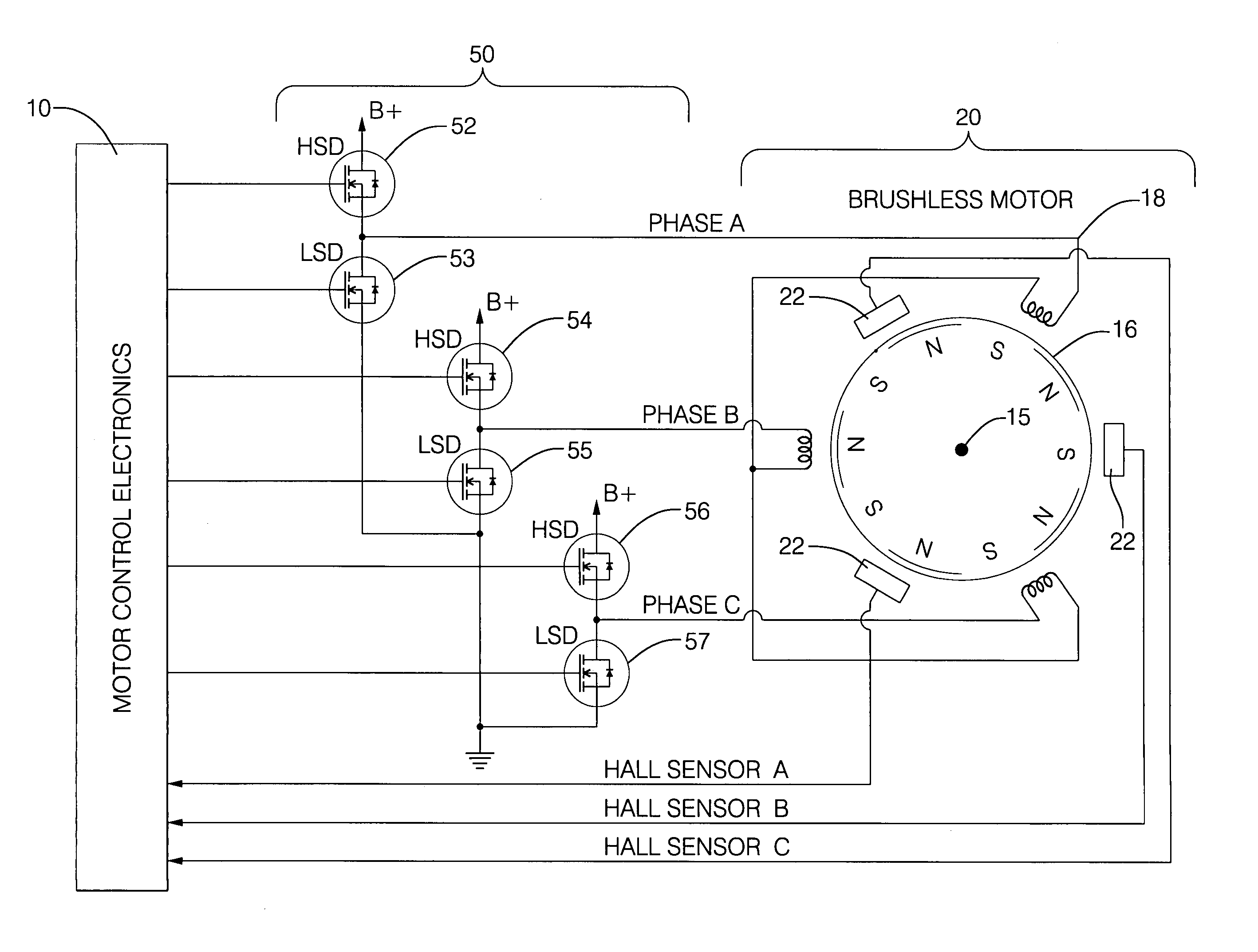
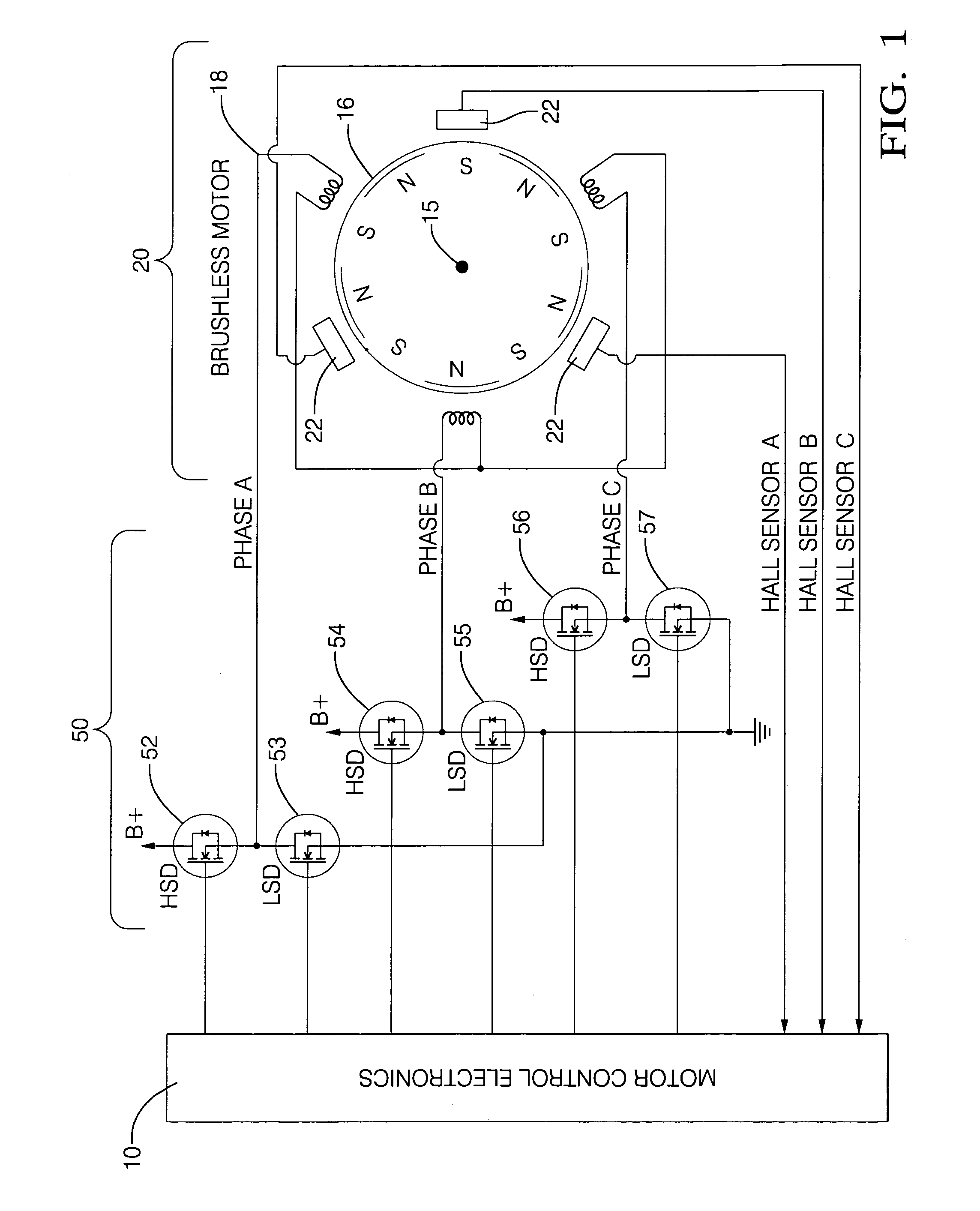
[0016]Referring now to the drawings, wherein the showings are for the purpose of illustrating the invention only and not for the purpose of limiting the same, FIG. 1 is a schematic of an exemplary circuit which has been constructed in accordance with an embodiment of the present invention.

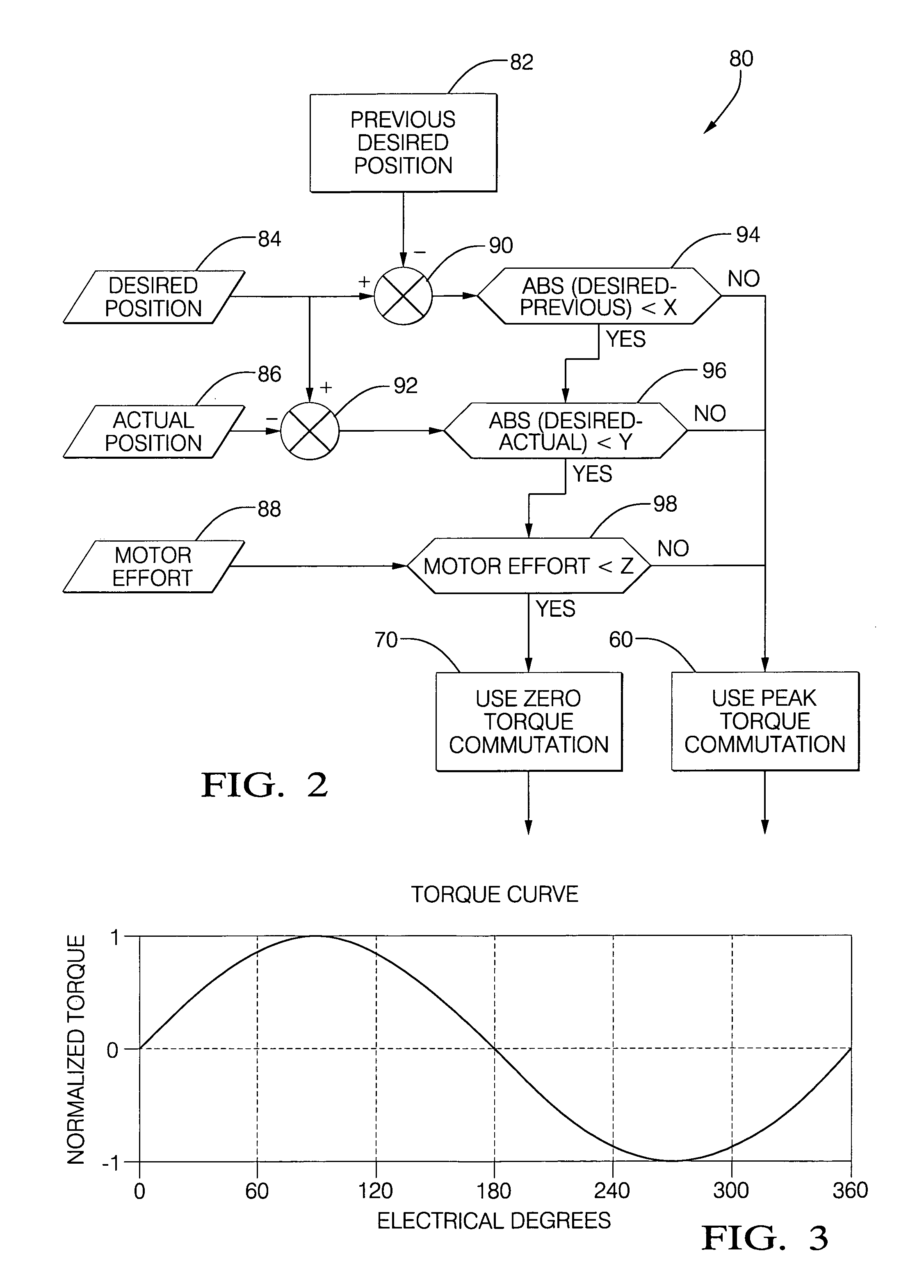
[0017]The exemplary circuit includes: a brushless motor 20 having an output shaft 15 and at least one position sensor 22; a motor drive circuit 50 comprising a plurality of field-effect transistors (“FET”) 52, 53, 54, 55, 56, 57 operable to control electrical current to the stator of brushless motor 20; and, an electronic controller 10, operable to monitor position of the brushless motor 20 based upon input from the position sensors 22, and operable to execute a plurality of predetermined algorithms 80 with calibrated thresholds to control each of the plurality of FETs, thus causing rotation of the brushless motor 20 about the output shaft 15. The output shaft 15 of the brushless DC motor 20 is pre...


PUM


Abstract

A method and control system to control a brushless DC motor to a preferred position is provided. The advantages that accrue to a system employing the method and apparatus to control the brushless DC motor to a preferred position include optimizing response time, energy usage, coil heating, and ability to hold to a fix position. The method to control the brushless DC motor to a position comprises monitoring actual position of the brushless DC motor, monitoring energy used by the brushless DC motor, and determining a commanded position of the brushless DC motor. A zero torque commutation method is employed to control the brushless DC motor to the commanded position only when a time-rate change in the commanded position is less than a first threshold, a difference between the commanded position and actual position is less than a second threshold, and, the monitored energy used is less than a third threshold. A peak torque commutation method is employed to control the brushless DC motor to achieve the commanded position when the time-rate change in the commanded position is greater than the first threshold, the difference between the commanded position and actual position is greater than the second threshold, or the monitored energy used is greater than the third threshold.

Description

TECHNICAL FIELD[0001]This invention pertains generally to a method and system to control a brushless DC motor, and a system that employs a brushless DC motor.BACKGROUND OF THE INVENTION[0002]A brushless DC motor of the present invention is a brushless DC motor comprising a rotor with an attached permanent magnet, and a stator. The rotor with attached permanent magnet is assembled on a shaft and inserted in the stator, and the rotor and shaft are operable to spin within the stator on one or more bearings, when electrically excited.[0003]Typical applications for a brushless DC motor on a powertrain for a vehicle may include, by way of example, a smart remote actuator for a cruise control system, an actuator and control device for a variable geometry turbocharger, or an exhaust gas recirculation valve actuator.[0004]There are many schemes for controlling a brushless DC motor, depending upon the application of the motor, complexity of the motor, and types of feedback control devices use...

Claims


Application Information

Patent Timeline
Patent Type & Authority Patents(United States)
IPC IPC(8): G05D13/00
CPCH02P8/42H02P6/16
Inventor HAZELTON, LAWRENCE DEAN
Owner DELPHI TECH IP LTD
Why Eureka
Try Eureka