Single wire digital interface
- Summary
- Abstract
- Description
- Claims
- Application Information
AI Technical Summary
Benefits of technology
Problems solved by technology
Method used
Image

Examples
Embodiment Construction
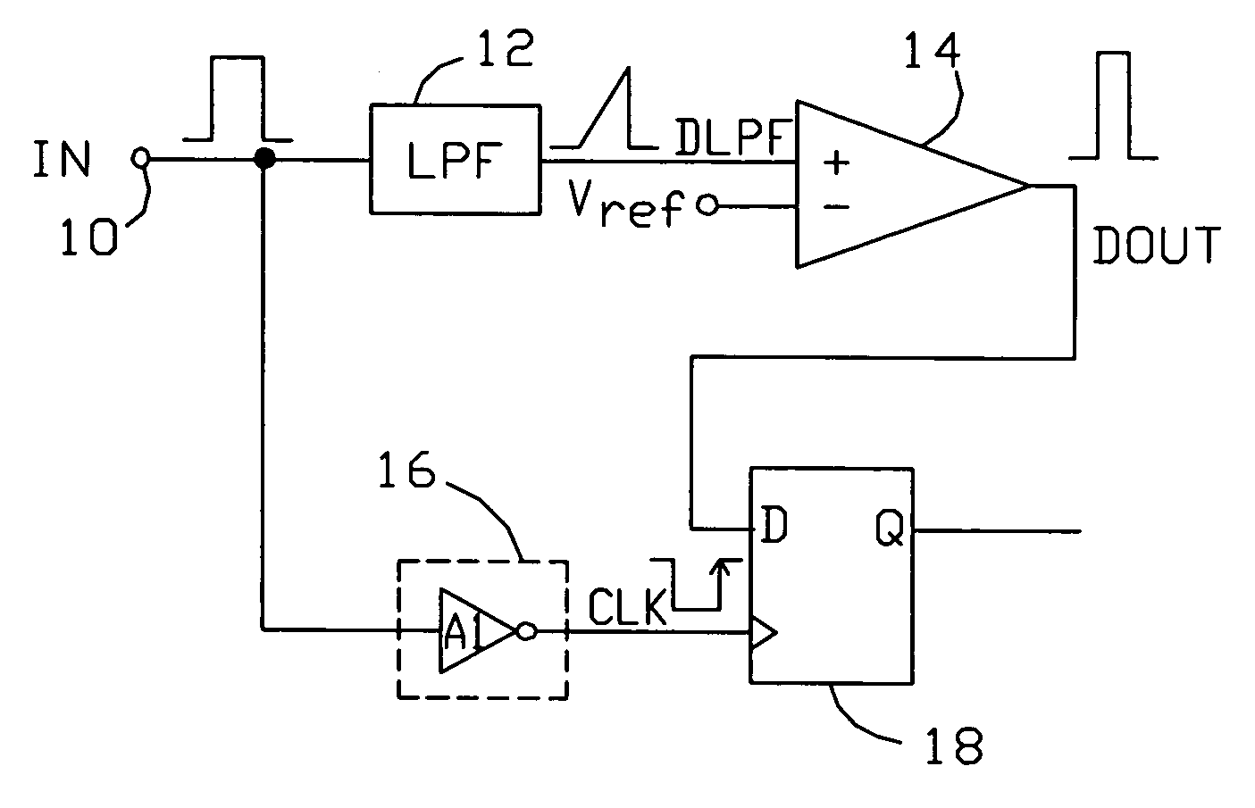
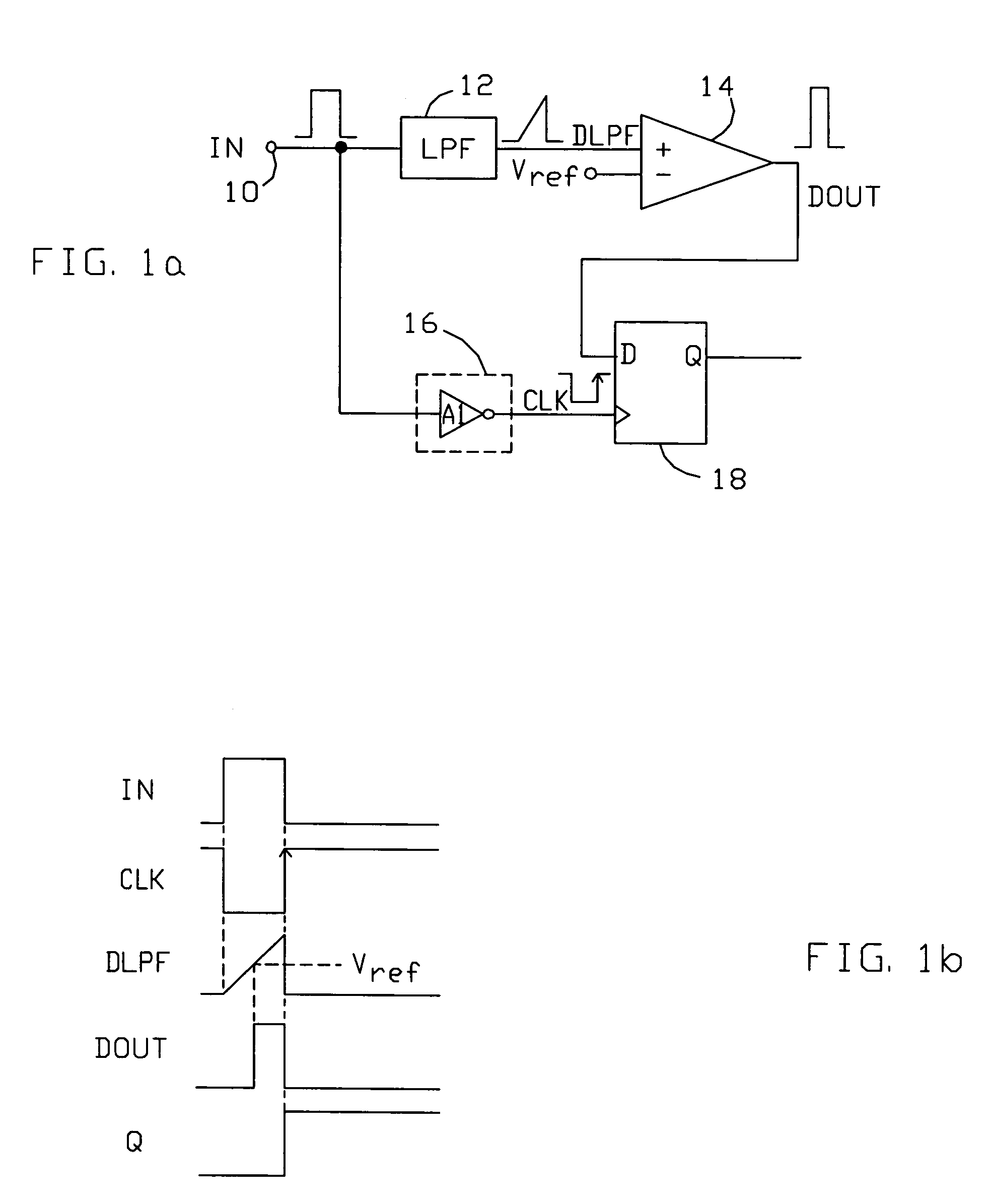
[0017]A diagram illustrating the operation of the present single-wire digital interface is shown in FIG. 1a. The interface is arranged to receive digital data as a stream of pulses, with ‘1’ and ‘0’ logic levels represented with pulses having defined “first” and “second” pulse widths, respectively. The interface comprises an input node 10 which receives the digital data pulses. The received pulses are applied to the input of a low-pass filter 12, which produces an output DLPF that increases at a known rate for the duration of a received pulse. Signal DLPH is applied to an input of a comparator 14, the output of which (DOUT) toggles when DLPH exceeds a predetermined threshold (represented here as an external reference Vref, though an internal reference might also be used). A clock generator 16, here implemented with an inverter A1, is connected to input node 10 and produces a clock signal CLK having an edge when a received pulse terminates. Clock signal CLK and comparator output sign...
PUM
 Abstract
Description
Claims
Application Information
 - Generate Ideas
- Intellectual Property
- Life Sciences
- Materials
- Tech Scout
- Unparalleled Data Quality
- Higher Quality Content
- 60% Fewer Hallucinations
Browse by: Latest US Patents, China's latest patents, Technical Efficacy Thesaurus, Application Domain, Technology Topic, Popular Technical Reports.
© 2025 PatSnap. All rights reserved.Legal|Privacy policy|Modern Slavery Act Transparency Statement|Sitemap|About US| Contact US: help@patsnap.com