Audio amplifier circuit with suppression of unwanted noise when starting from an off or standby state

Active Publication Date: 2006-05-30
STMICROELECTRONICS SRL
View PDF7 Cites 18 Cited by
  • Summary
  • Abstract
  • Description
  • Claims
  • Application Information

AI Technical Summary

Benefits of technology

[0016]The present invention also aims at providing such a circuit which makes little or no unwanted noise at the starting of the circuit from a stopped state or a standby state.
[0017]The present inventi

Problems solved by technology

However, such circuits are impossible to use in small-size devices such as mobile phones or walkmans due to the bulk of the relay, which is difficult to integrate.
However, this improvement is obtained at the cost of a significant lengthening of the latency time, that is the startin

Method used


Image

  • Audio amplifier circuit with suppression of unwanted noise when starting from an off or standby state
  • Audio amplifier circuit with suppression of unwanted noise when starting from an off or standby state
  • Audio amplifier circuit with suppression of unwanted noise when starting from an off or standby state

Examples


Example

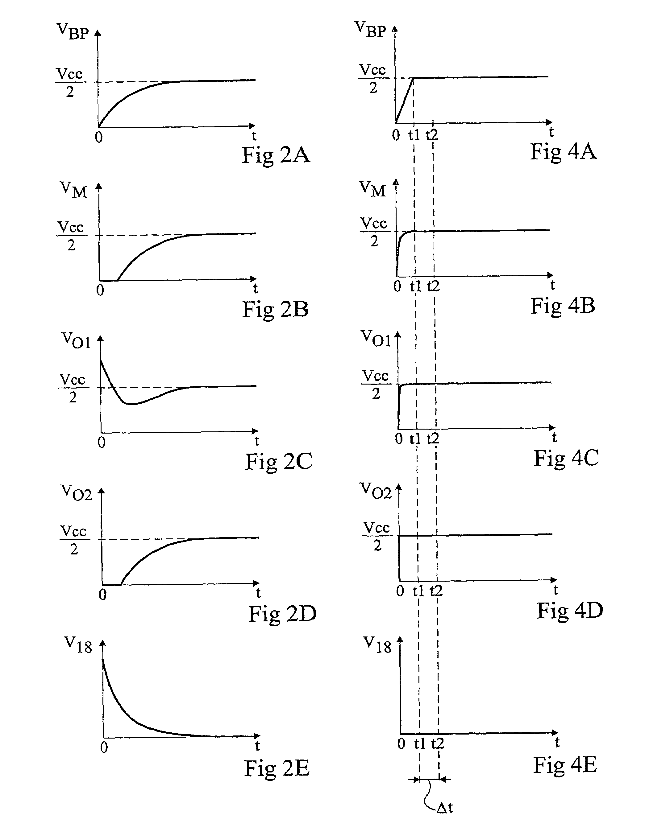
[0039]For clarity, the same reference numerals designate the same elements in the different drawings. Further, the timing diagrams of FIGS. 2A to 2E and 4A to 4E are not to scale.

[0040]A feature of the present invention is, upon starting from an off or standby state, to separately charge the coupling and decoupling capacitors of a bridge amplifier circuit while operational amplifiers of the bridge circuit are inhibited. Such a separate charge is maintained, preferably, at least as long as the charge level of the decoupling capacitor is smaller than a given reference level.

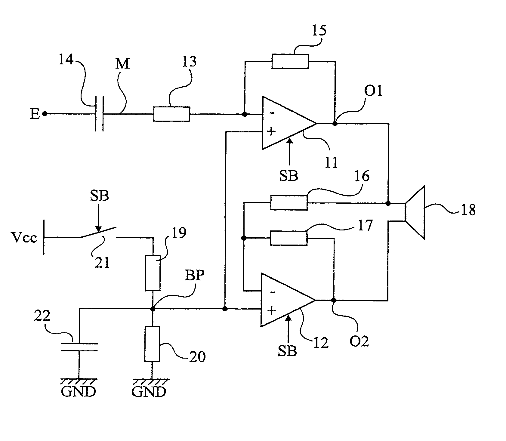
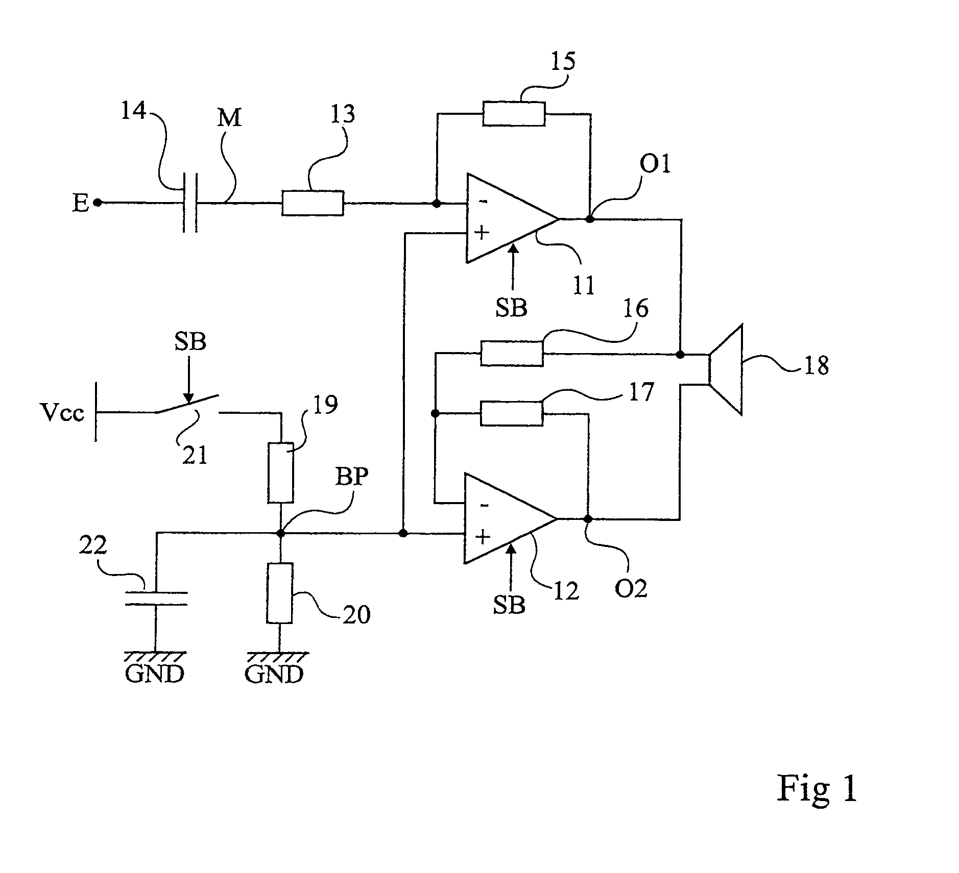
[0041]FIG. 3 shows an example of the architecture of an amplifier circuit according to an embodiment of the present invention. The amplifier circuit comprises a bridge assembly with the same cascade structure of the two amplifiers 11 and 12 as shown in FIG. 1. For simplicity, only the differences between FIG. 1 and FIG. 3 will be described hereafter.

[0042]According to an aspect of the present invention, the amplifi...


PUM


Abstract

A power amplifier circuit including first and second cascade-assembled operational amplifiers having respective first inputs receiving a reference voltage across a decoupling capacitor, respective outputs of which are connected across a load and are looped back on respective second inputs, the second input of the first amplifier receiving, from a coupling capacitor, an input voltage to be amplified, the amplifier circuit including means for separately charging the coupling and decoupling capacitors, upon circuit power-on, from an off or standby state, and means for inhibiting the amplifiers at least during the separate charging.

Description

BACKGROUND OF THE INVENTION[0001]1. Field of the Invention[0002]The present invention relates to an amplifier circuit used in audio systems.[0003]2. Discussion of the Related Art[0004]FIG. 1 shows a conventional audio bridge tiled load (BTL) amplifier circuit. The circuit comprises two inverter-assembled operational amplifiers 11 and 12. The inverting input (−) of amplifier 11 is connected to an input terminal E of the system by a resistor 13 and a coupling capacitor 14 connected in series. Output O1 of amplifier 11 is connected to its inverting input (−) by a resistor 15. The inverting input (−) of amplifier 12 is connected to output O1 of amplifier 11 by a resistor 16 and to its output O2 by a resistor 17. The respective outputs O1 and O2 of amplifiers 11 and 12 are connected to the terminals of a load 18, typically a loudspeaker capable of emitting sounds according to the current flowing therethrough. The non-inverting inputs (+) of amplifiers 11 and 12 are connected to a common ...

Claims


Application Information

Patent Timeline
IPC IPC(8): H03F3/45H03F1/30H03F3/183H03F3/187H03F3/72
CPCH03F1/305H03F1/307H03F3/72H03F3/187H03F3/183
Inventor FOREL, CHRISTOPHECITTADINI, ROBERT
Owner STMICROELECTRONICS SRL
Why Eureka
Try Eureka