Rotational speed detector with ripple compensation

Inactive Publication Date: 2006-05-30
TOSHIBA ELEVATOR KK
View PDF7 Cites 6 Cited by
  • Summary
  • Abstract
  • Description
  • Claims
  • Application Information

AI Technical Summary

Problems solved by technology

Since torque ripples are caused by speed irregularities and positional displacement of the support motor, they adversely affect the processing precision in, for example, an NC (numerical control) apparatus, and spoil the smoothness of an elevator ride by increasing carriage shaking.
However, when the ripples are caused by the angle of rotation being detected in the output value of the rotation detecting sensor, the amplitude of the ripples becomes larger in proportion to the detected angle speed, leading to a problem that it becomes impossible to increase the angle speed feedback gain when controlling the torque of the motor and the rotat

Method used


Image

  • Rotational speed detector with ripple compensation
  • Rotational speed detector with ripple compensation
  • Rotational speed detector with ripple compensation

Examples


embodiment 1

[0051]A first embodiment of this invention will be explained with reference to FIGS. 1 to 7.

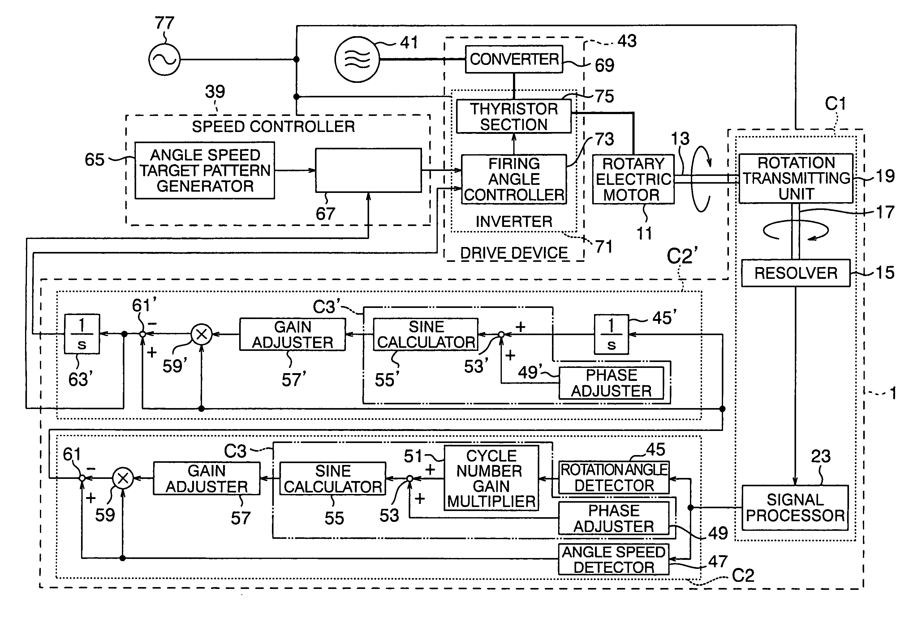
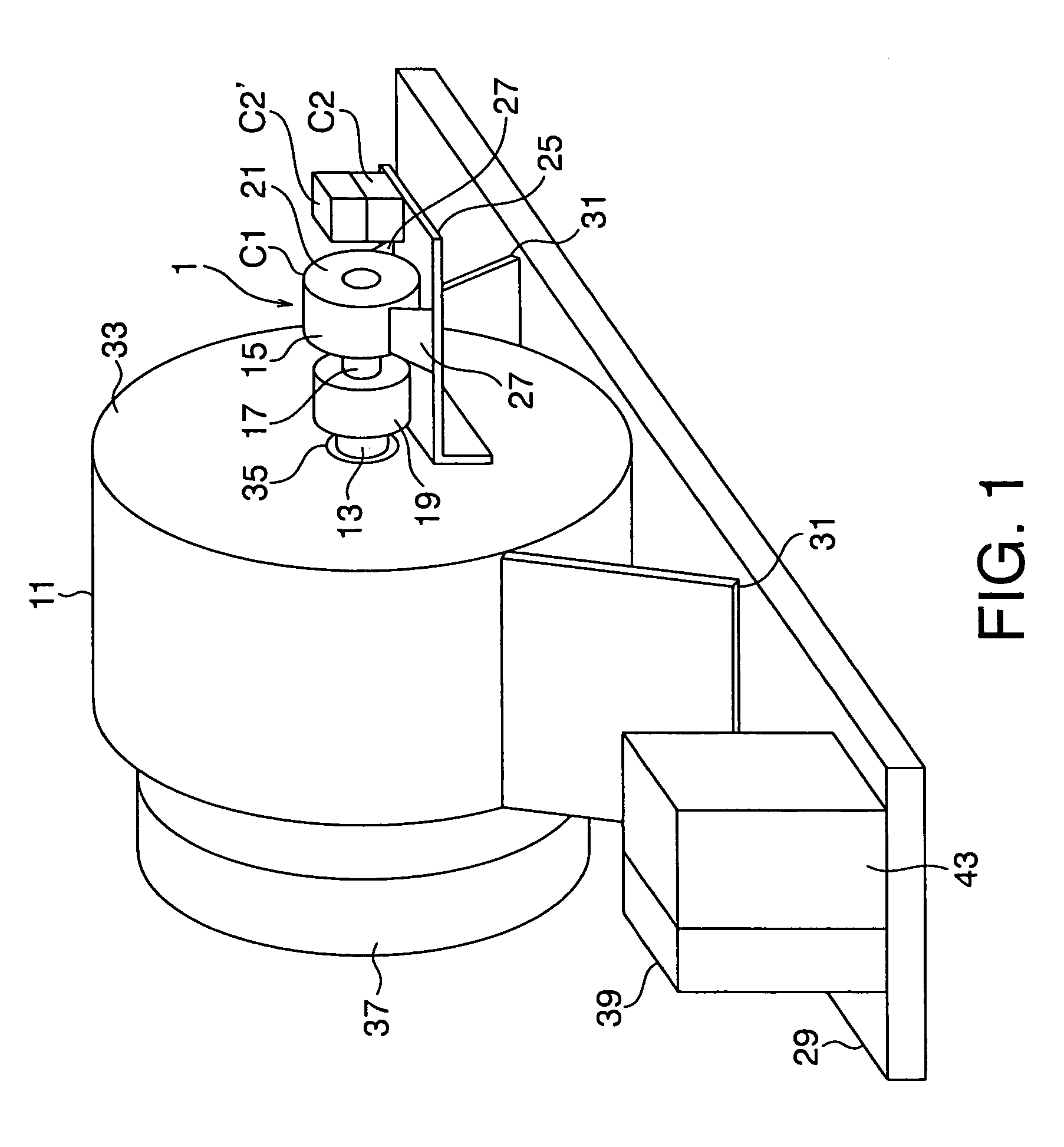
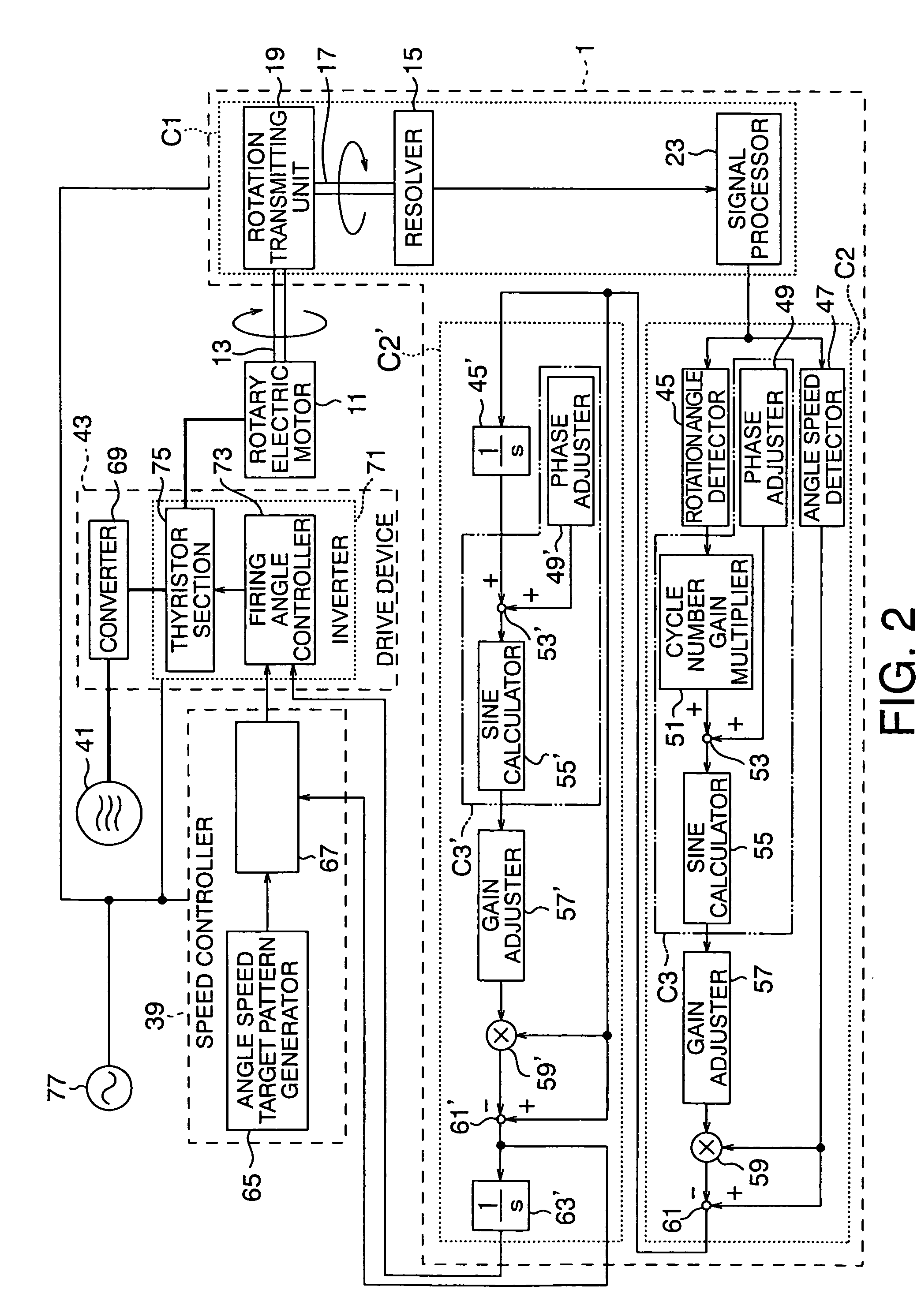
[0052]In FIGS. 1 and 2, reference code 1 represents the overall rotary detector in a first embodiment. The rotary detector 1 comprises a rotary detector unit C1, and rotary calculator units C2 and C2′.

[0053]The rotary detector unit C1 of this embodiment is attached to the device being detected, here comprising a rotor rotating axis 13 of a rotary electric motor 11, and comprises a resolver 15 which outputs a voltage proportionate to the rotation angle of the rotor rotation axis 13, a rotation input axis 17 which is directly connected to an unillustrated rotor of the resolver 15, and a rotation transmitting unit 19 which connects to the rotor rotation axis 13 and transmits rotations of the rotor rotation axis 13 to the rotation input axis 17 of the resolver 15.

[0054]The rotation transmitting unit 19 comprises, for example, a universal joint and a coupler, and the rotation input axis 17 of the ...

embodiment 2

[0067]Subsequently, a second embodiment of this invention will be explained with reference to FIGS. 8 and 9.

[0068]In the first embodiment, the output signal of the rotary detector unit C1 is processed by the rotary calculation units C2 and C2′, which are provided in series. However, there are no restrictions on the number and constitution of rotary calculation units, which may be modified in accordance with the features of the ripple component in the signal output by the rotary detector. For example, in a rotary detector unit C1′ comprising a rotary encoder 87 instead of the j15, there is no second ripple component caused by the j15. On the other hand, when there is backlash in the rotation transmitting unit 19 comprising a coupling, the adjust phase fluctuates in accordance with the torque direction of the rotary electric motor 11. When the negative load of the rotary electric motor 11 exerts an external force against the rotor rotating axis 13 in a direction warping the axis core,...

embodiment 3

[0070]A third embodiment of this invention will be explained with reference to FIGS. 10 and 11.

[0071]In the first and second embodiments, the rotary detection units (C1 and C1′) are adjacent to the rotary calculation units (C2, C2′, and C2″), and together form the overall rotary detector 1, but there are no restrictions on the distance and positions of the rotary detection units and rotary calculation units. As shown in FIGS. 10 and 11, the rotary calculator unit C2 may be incorporated in the speed control device 39 and the drive device 43. Since the drive device 43′ requires rotation angle information, the output of the rotary calculator unit C2 is input via the integrator 63′ to the firing angle controller 73. The rotary calculator unit C2′ is not used here, since the first ripple component caused by the rotary transmitting unit is negligible. In this embodiment, the rotary detector unit C1 may be installed in the rotary electric motor 11, achieving an advantage of simple installa...


PUM


Abstract

The rotary detector according to this invention comprises a rotary detector unit C1, C1′ which detects rotary motion of a rotor; and a rotary calculator unit C2, C2′, C2″ comprising a rotation angle detector, which detects the rotation angle of the rotor, and an angle speed detector 47 which detects the angle speed of the rotor, based on the output of the rotary detector unit. The rotary calculator unit comprises a trigonometrical calculator C3, C3′, C3″ which calculates a sine value or a cosine value of the rotation angle detected by the rotary detector; a gain adjuster 57, 57′, 57″ which multiplies the sine value or the cosine value, calculated by the trigonometrical calculator, by a predetermined gain; a multiplier 59, 59′ which multiplies the output of the gain adjuster by the output of the angle speed detector; and a subtracter 61, 61′ which subtracts the output of the multiplier from the output of the angle speed detector.

Description

[0001]This application is a 371 of PCT / JP02 / 095 15 filed Sep. 17, 2002 which claims benefit of Japanese patent 2001-280030 filed Sep. 14, 2001.BACKGROUND OF THE INVENTION[0002]1. Field of the Invention[0003]The present invention relates to a rotary detector which can reduce the torque ripple of a rotor and the like by reducing the ripple component of an output signal.[0004]2. Description of the Related Art[0005]The output torque of a motor generally contains ripples. Since torque ripples are caused by speed irregularities and positional displacement of the support motor, they adversely affect the processing precision in, for example, an NC (numerical control) apparatus, and spoil the smoothness of an elevator ride by increasing carriage shaking.[0006]When detecting this type of torque ripple, the torque ripple may be internal, arising in the motor main body comprising an accelerator, or external, arising in a rotary detecting sensor. Internal torque arises from the work precision of...

Claims


Application Information

Patent Timeline
IPC IPC(8): G01P3/00G01P3/46B66B1/34G01D5/244G01D5/245G01P3/48G01P3/489H02K11/00H02K24/00H02K29/03H02K29/06H02K29/14H02P6/10
CPCB66B1/3492G01P3/48G01P3/489H02K11/0015H02K11/0026H02P6/10H02K11/0073H02K29/06H02K29/14H02K11/0031H02K29/03H02K11/21H02K11/22H02K11/225H02K11/33G01P3/46
Inventor MORISHITA, MIMPEI
Owner TOSHIBA ELEVATOR KK
Why Eureka
Try Eureka