Radiation treatment plan making system and method
a treatment plan and radiation treatment technology, applied in the field of radiation treatment system, can solve the problems of low and achieve the effect of increasing the efficiency of particle beams and maintaining flatness
- Summary
- Abstract
- Description
- Claims
- Application Information
AI Technical Summary
Benefits of technology
Problems solved by technology
Method used
Image
Examples
first embodiment
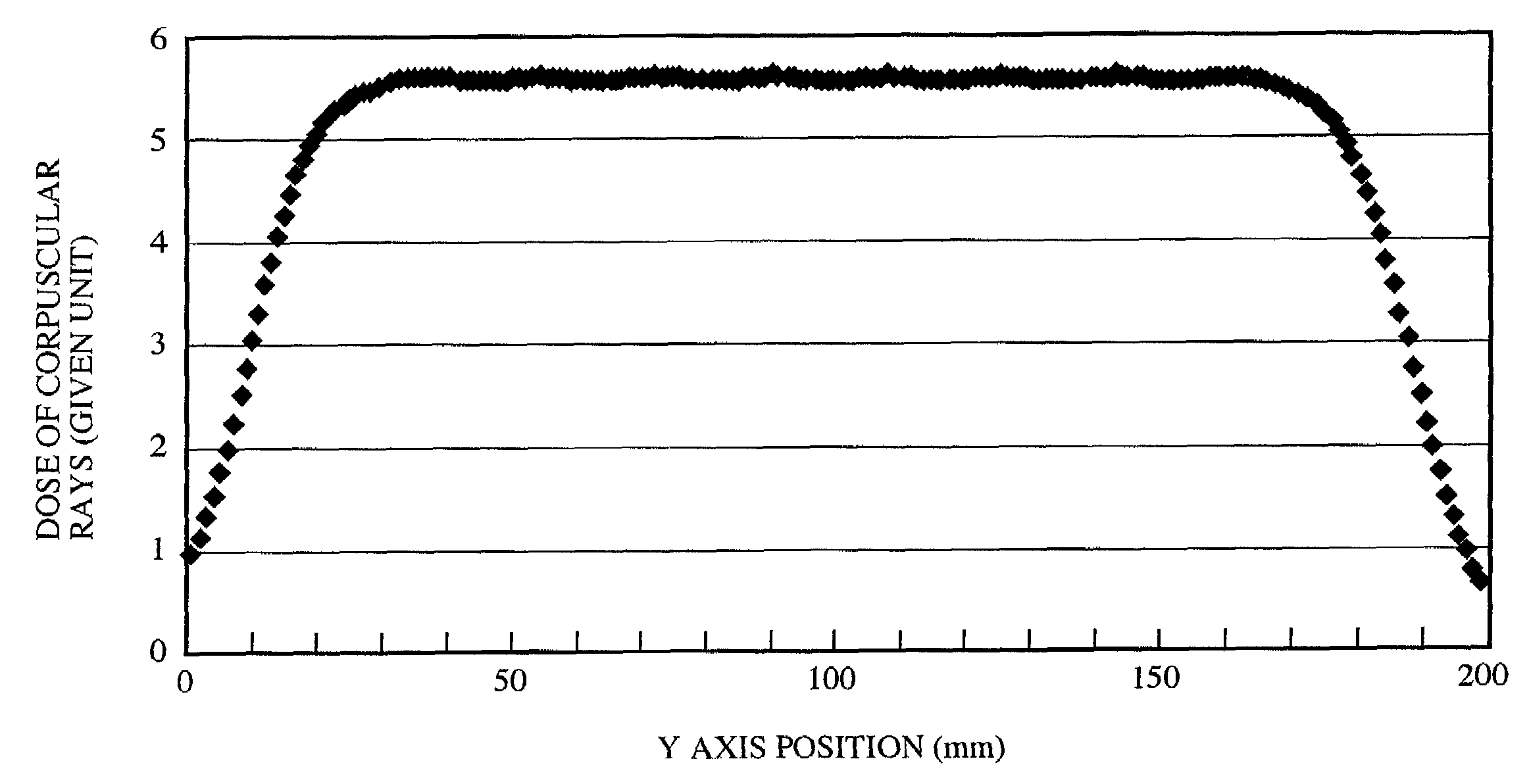
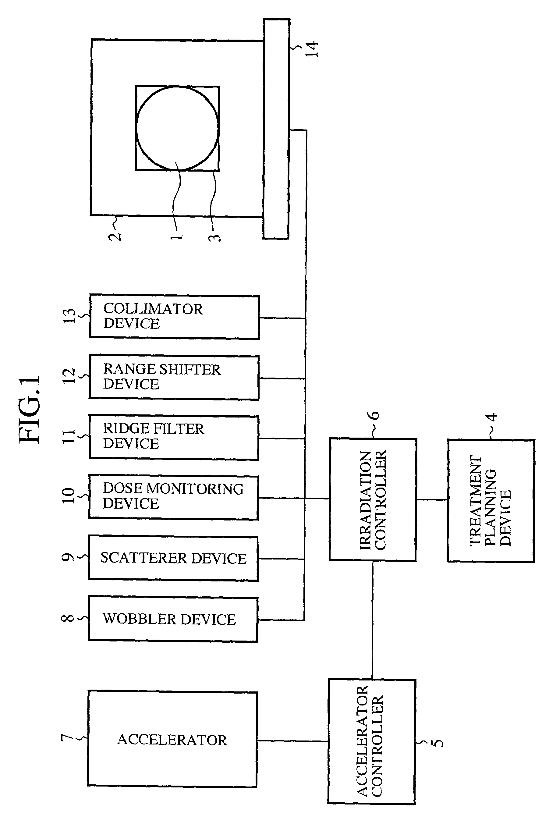
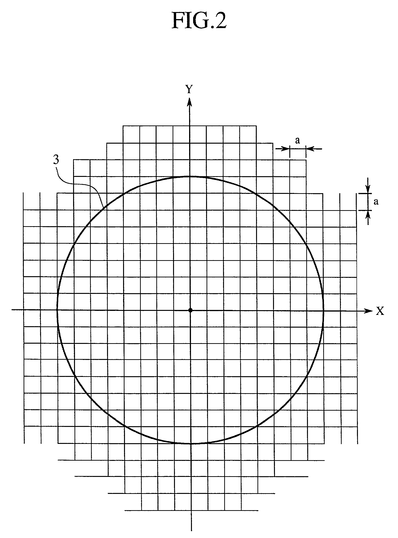
[0044]FIG. 1 illustrates the configuration of a radiation treatment system according to the first embodiment of the invention. In the drawing, a reference numeral 1 denotes a treatment region, in which a tumor or the like is present to be subjected to radiation treatment, which treatment region being assumed to be a ball having a radius r, and the center thereof being located at a cubic center of a patient 2 assumed to be a cube having one side set to 4r; 2 a patient fixed to a treatment couch 14, and subjected to radiation exposure; 3 a radiation exposure region to be irradiated with particle beams, defined by a three-dimensional region including the treatment region 1; and 4 a treatment planning device (simulation means and irradiation planning means), adapted to form a radiation exposure region 3 according to the state of the diseased part of the patient 2, divide the thus formed radiation exposure region 3 and the peripheral region thereof in a grid form, and set a control param...
second embodiment
[0081]The radiation treatment system of the second embodiment is basically similar in configuration to that of the first embodiment. Thus, description will be made of portions different from those of the first embodiment.
[0082]First, the treatment planning device 4 (simulation means and irradiation planning means) of the second embodiment forms a radiation exposure region 3 according to the state of the diseased part of the patient 2 to be treated as in the case of the first embodiment, divides the radiation exposure region 3 and the peripheral region thereof into belt forms, and then sets a control parameter (radiation treatment condition) of each device for applying particle beams according to the center Line of the belt form (unit radiation exposure region) in the accelerator controller 5 and the irradiation controller 6. The accelerator controller 5 and the irradiation controller 6 execute treatment simulation for applying particle beams according to the center Line of the belt ...
third embodiment
[0119]The radiation treatment system of the third embodiment is basically similar in configuration to that of the first embodiment. Thus, portions different from those of the first embodiment will be described.
[0120]First, the treatment planning device 4 (simulation means and irradiation planning means) of the third embodiment forms a radiation exposure region 3 according to the state of the diseased part of the patient 2 as in the case of the first embodiment, divides the radiation exposure region 3 and the peripheral region thereof in concentric circular forms, and then sets a control parameter (radiation treatment condition) of each device for applying particle beams according to the center line of the interval of the concentric circles (unit radiation exposure region) in the accelerator controller 5 and the irradiation controller 6. The accelerator controller 5 and the irradiation controller 6 execute treatment simulation for applying particle beams according to the center line ...
PUM
 Abstract
Description
Claims
Application Information
 - R&D
- Intellectual Property
- Life Sciences
- Materials
- Tech Scout
- Unparalleled Data Quality
- Higher Quality Content
- 60% Fewer Hallucinations
Browse by: Latest US Patents, China's latest patents, Technical Efficacy Thesaurus, Application Domain, Technology Topic, Popular Technical Reports.
© 2025 PatSnap. All rights reserved.Legal|Privacy policy|Modern Slavery Act Transparency Statement|Sitemap|About US| Contact US: help@patsnap.com


