Network synchronization technique
a network and synchronization technology, applied in the field of communication networks, can solve the problems of adversely affecting the quality of image and sound reproduced from the received av stream, adversely affecting the transmission quality of the received real-time stream, and media-dependent frequency not synchronizing with frequency, so as to reduce the frequency fluctuations of the isochronous cycle
- Summary
- Abstract
- Description
- Claims
- Application Information
AI Technical Summary
Benefits of technology
Problems solved by technology
Method used
Image
Examples
first embodiment
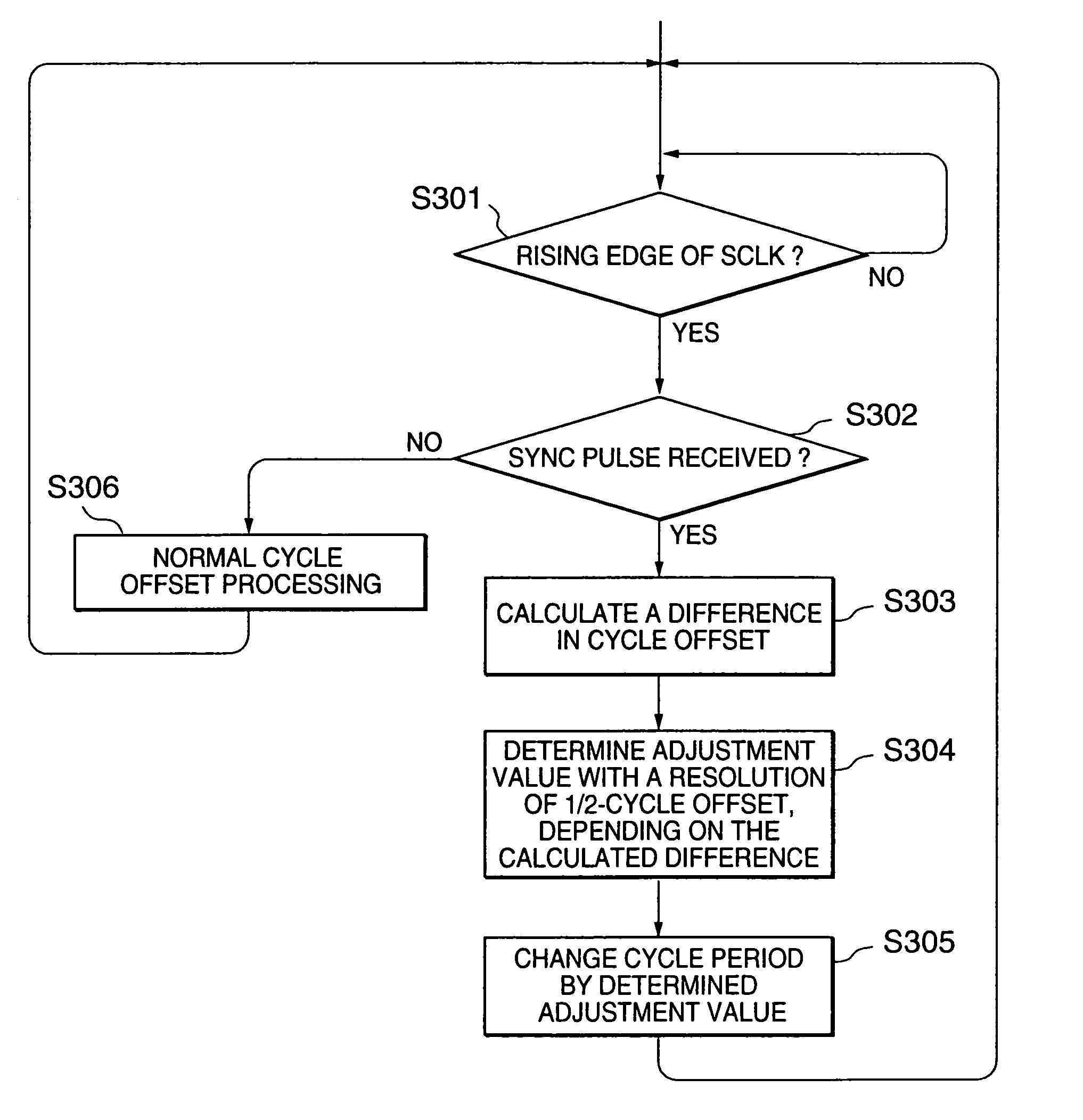
[0072]The overwriting of the cycle time register provided in a network device will be described when a cycle start packet has been received from a cycle master.
1.1) Link-Layer LSI
[0073]Referring to FIG. 6, a 1394 link-layer LSI 20A is employed in a node of, for example, the IEEE1394 network as shown in FIG. 1. The 1394 link-layer LSI 20A is provided with a physical-layer / link-layer (PHY / LINK) interface 110 through which plural signals (e.g. in the neighborhood of nine kinds of signals) are inputted and outputted from and to the PHY LSI. In FIG. 6, however, only a system clock signal SCLK and data are depicted. The system clock signal SCLK is received from the PHY LSI. As for data, the PHY / LINK interface 110 is a bidirectional interface to the PHY LSI to exchange packets.
[0074]The 1394 link-layer LSI 20A operates according to the system clock signal SCLK, which has a frequency fs of 49.152 MHz, that is, two times the clock frequency of the crystal oscillator provided in the PHY LSI (...
second embodiment
2.1) Digital Video Player
[0091]Referring to FIG. 11, a digital video player 220 employs a link-layer LSI 20C according to a second embodiment of the present invention. The digital video player 220 further includes a PHY LSI 10, a processor (CPU) 170, a ROM 180, RAM 190, a decoder 200, and a digital-to-analog converter 210. The digital video player 220 decodes a digital video signal of DV format received from the IEEE1394 bus and outputs an analog video signal.
[0092]The digital video signal of DV format is mapped into isochronous stream packet following IEC 61883 standard. More specifically, the upper eight bytes of the data field of an isochronous stream packets are defined as a header of a common isochronous packet (CIP) in the IEC 61883 standard, The type of video format and time stamp information are stored in the CIP header.
[0093]The link-layer LSI 20C has a host interface to a host bus connected to other components including the processor (CFU) 170 and a stream interface to the...
third embodiment
3.1) Bridge Network
[0109]Referring to FIG. 15, it is assumed that a bridge 70A connects two IEEE1394 buses 90 and 91 and the bridge 70A is composed of portals 80A and 80B, which are connected to the buses 90 and 91, respectively. The respective buses 90 and 91 are connected to nodes 50 and 51.
[0110]In this embodiment, the node 50 functions as a cycle master of the bus 90 and a net cycle master for the entire bridge network. On the other hand, the portal 80 of the bridge 70A functions as a cycle master of the bus 91. Therefore, the bridge 70A performs synchronization of the portal 80B to the portal 80A. The portal 80A is a master portal and the portal 80B is a slave portal. The slave portal 80B as the cycle master of the bus 91 notifies the bus 91 by a cycle start packet of time information obtained by the cycle time register control, so that synchronization is established in the entire bridge network.
3.2) Bridge
[0111]Referring to FIG. 16, the bridge 70A includes an inter-bus synchro...
PUM
 Abstract
Description
Claims
Application Information
 - R&D
- Intellectual Property
- Life Sciences
- Materials
- Tech Scout
- Unparalleled Data Quality
- Higher Quality Content
- 60% Fewer Hallucinations
Browse by: Latest US Patents, China's latest patents, Technical Efficacy Thesaurus, Application Domain, Technology Topic, Popular Technical Reports.
© 2025 PatSnap. All rights reserved.Legal|Privacy policy|Modern Slavery Act Transparency Statement|Sitemap|About US| Contact US: help@patsnap.com


