Method and apparatus for noise attenuation for gas turbine engines using at least one synthetic jet actuator for injecting air

a gas turbine engine and synthetic jet technology, applied in the direction of machines/engines, vessel construction, marine propulsion, etc., can solve the problems of adversely affecting the performance of the engine during all engine operating conditions, adversely affecting the specific fuel consumption of the engine, and substantial noise along the take-off path, etc., to achieve the effect of facilitating attenuating jet nois

Active Publication Date: 2006-06-06
GENERAL ELECTRIC CO
View PDF56 Cites 76 Cited by
  • Summary
  • Abstract
  • Description
  • Claims
  • Application Information

AI Technical Summary

Benefits of technology

[0006]In another aspect, an exhaust assembly for a gas turbine engine is provided. The exhaust assembly includes a flow boundary surface for channeling exhaust from the engine, an outlet for discharging exhaust from the engine, and a noise suppression sy

Problems solved by technology

During such operations, the high velocity flows interact with each other, well as ambient air flowing past the engine, and may produce substantial noise along the take-off path of the aircraft.
Although such devices do provide a noise reduction benefit during take-off conditions, because the chevron nozzle

Method used


Image

  • Method and apparatus for noise attenuation for gas turbine engines using at least one synthetic jet actuator for injecting air
  • Method and apparatus for noise attenuation for gas turbine engines using at least one synthetic jet actuator for injecting air
  • Method and apparatus for noise attenuation for gas turbine engines using at least one synthetic jet actuator for injecting air

Examples


Embodiment Construction

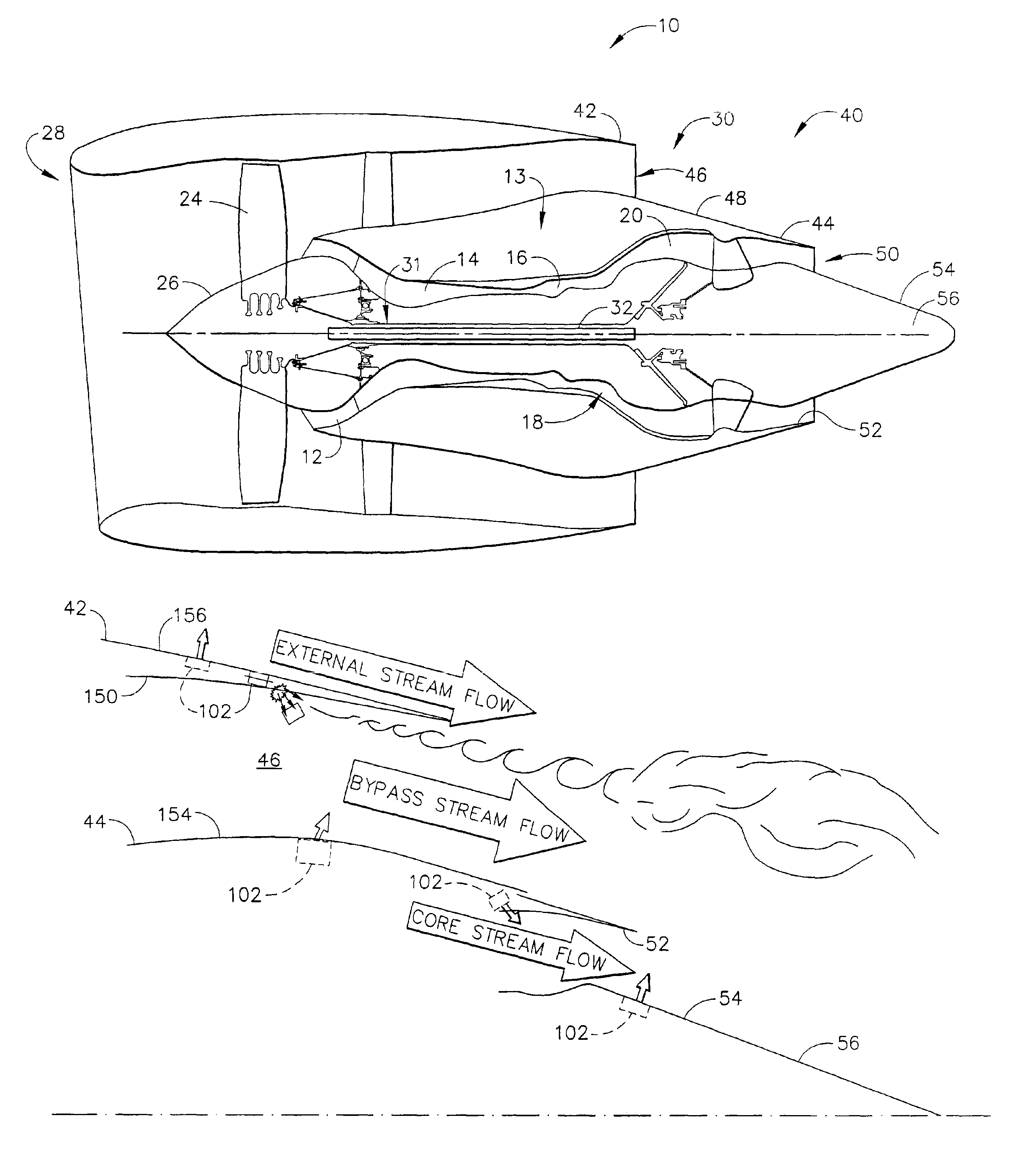
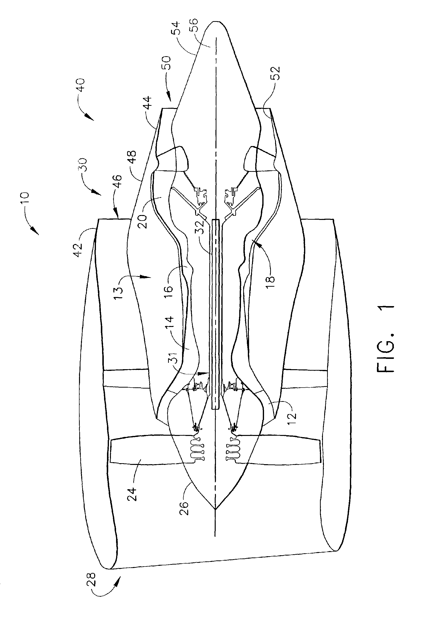
[0012]FIG. 1 is a schematic illustration of a gas turbine engine 10 including a fan assembly 12 and a core engine 13 including a high pressure compressor 14, and a combustor 16. Engine 10 also includes a high pressure turbine 18, a low pressure turbine 20, and a booster 22. Fan assembly 12 includes an array of fan blades 24 extending radially outward from a rotor disc 26. Engine 10 has an intake side 28 and an exhaust side 30. In one embodiment, the gas turbine engine is a GE90 available from General Electric Company, Cincinnati, Ohio. Fan assembly 12 and turbine 20 are coupled by a first rotor shaft 31, and compressor 14 and turbine 18 are coupled by a second rotor shaft 32.

[0013]An exhaust assembly 40 extends downstream from core engine 31 and includes an annular fan exhaust nozzle 42 that extends around, and is spaced radially outwardly from, a core engine exhaust nozzle 44. More specifically, fan exhaust nozzle 42 is positioned upstream from core exhaust nozzle 44 and is spaced ...


PUM


Abstract

A method enables a gas turbine engine to be operated. The method comprises channeling exhaust gases from a core engine through an exhaust assembly and past at least one flow boundary surface, and selectively operating a noise suppression system extending from the at least one flow boundary surface to facilitate attenuating noise generated during engine operation.

Description

BACKGROUND OF THE INVENTION[0001]This invention relates generally to gas turbine engines, more particularly to methods and apparatus for operating gas turbine engines.[0002]At least some known gas turbine engines include a core engine having, in serial flow arrangement, a fan assembly and a high pressure compressor which compress airflow entering the engine, a combustor which burns a mixture of fuel and air, and low and high pressure rotary assemblies which each include a plurality of rotor blades that extract rotational energy from airflow exiting the combustor.[0003]Combustion gases are discharged from the core engine through an exhaust assembly. More specifically, within known turbofan engines, a core exhaust nozzle is used to discharge core exhaust gases radially inwardly from a concentric fan exhaust nozzle which exhausts fan discharge air therefrom for producing thrust. Typically, both exhaust flows have a maximum velocity when the engine is operated during high power operatio...

Claims


Application Information

Patent Timeline
IPC IPC(8): F02C1/00F02K1/34F02K1/38
CPCF02K1/34F02K1/38F05D2260/962
Inventor MARTENS, STEVENSADDOUGHI, SEYED GHOLAMALIEARLY, KEVIN SEAN
Owner GENERAL ELECTRIC CO
Why Eureka
Try Eureka