
Multiple frequency Helmholtz resonator

Inactive Publication Date: 2006-06-06
CARRIER CORP
View PDF14 Cites 30 Cited by
  • Summary
  • Abstract
  • Description
  • Claims
  • Application Information

AI Technical Summary

Benefits of technology

[0004]It is an object of this invention to eliminate the need for a resonator for each frequency of interest at both high and low speed operation.

Problems solved by technology

These tones can be sources of annoyance in the community adjacent areas where a number of units are running.

Method used


Image

  • Multiple frequency Helmholtz resonator
  • Multiple frequency Helmholtz resonator
  • Multiple frequency Helmholtz resonator

Examples


Embodiment Construction

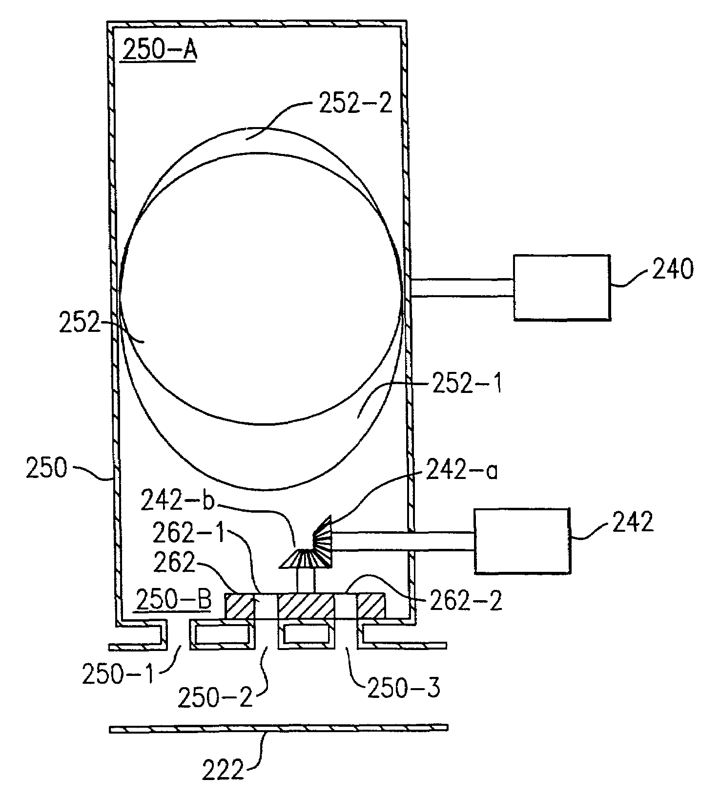
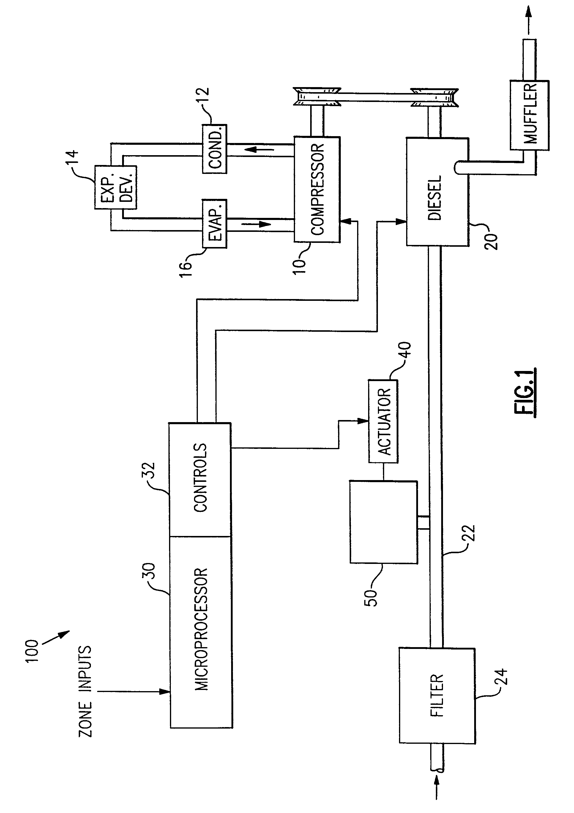
[0016]In FIG. 1, the numeral 100 generally designates a transport refrigeration system. Refrigeration compressor 10 is driven by a multi-speed diesel engine 20. Compressor 10 is in a refrigeration circuit serially including condenser 12, expansion device 14 and evaporator 16. Refrigeration system 100 is controlled by microprocessor 30 which receives a number of inputs such as the engine speed, the sensed ambient temperature, condenser entering air temperature, zone temperature, and zone set point which are collectively labeled as zone inputs. In operation, diesel engine 20 and compressor 10 are driven though controls 32 responsive to microprocessor 30. Specifically, diesel engine 20 may be driven through a speed control solenoid and draw ambient air into its cylinders via inlet line 22 containing filter 24.

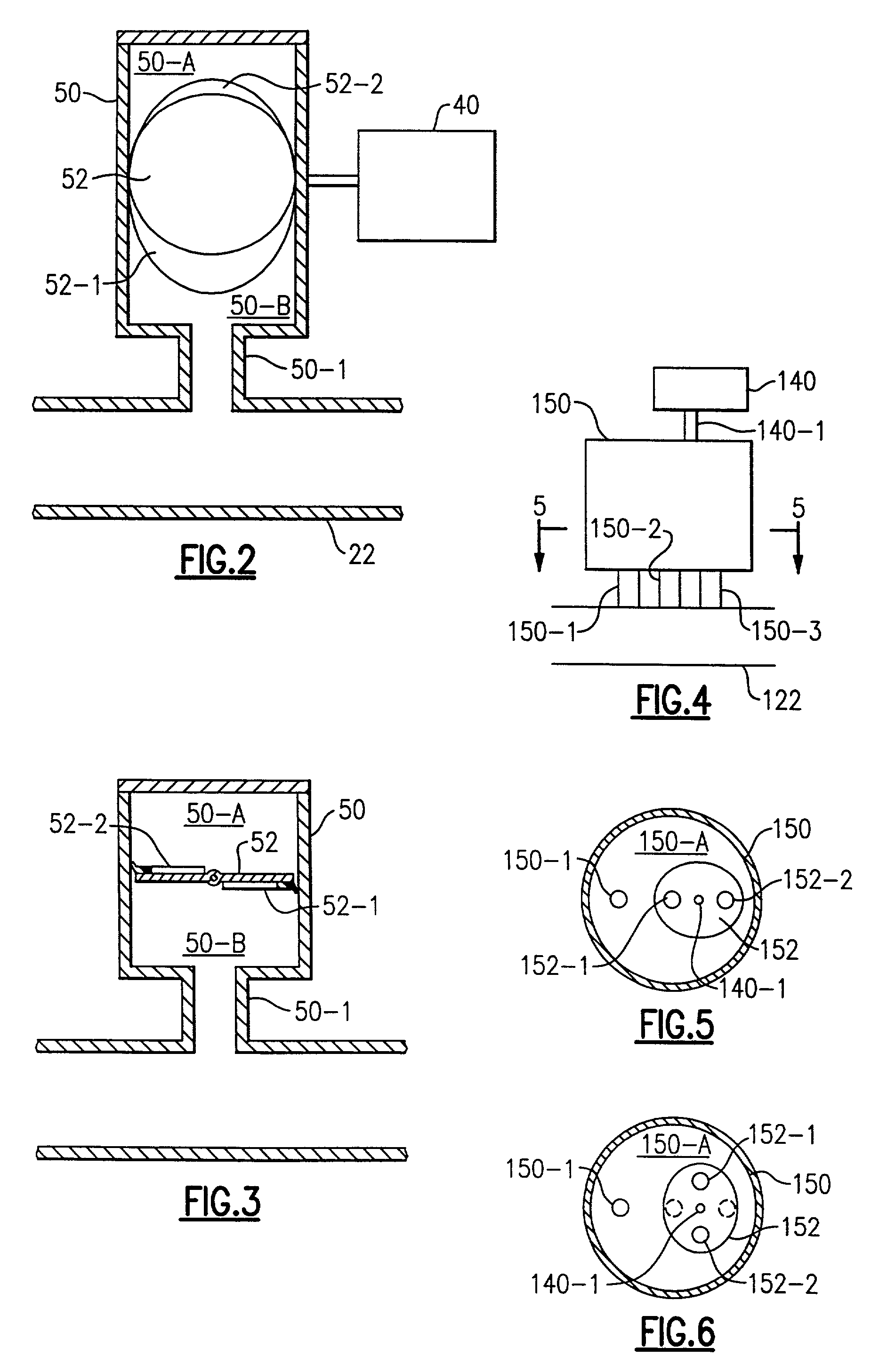
[0017]The present invention changes the frequency range to which a Helmholtz resonator is responsive by varying the effective volume of the resonator, or varying the neck area or ...


PUM


Abstract

The tunable resonator is coupled to the engine speed control such that the resonator is set to a different frequency range when the engine speed is changed. The frequency range is changed by opening and closing necks and / or changing the effective volume of the resonator.

Description

BACKGROUND OF THE INVENTION[0001]Diesel engines used to drive transport refrigeration equipment produce low frequency tones at their firing frequencies and their harmonics. The refrigeration units can be required to hold the load temperature within 0.1F.° of the set point which may be 40° F. for flowers or produce and −20° F. for ice cream. A number of these units can be parked and running at cold storage warehouses, interstate highway rest stops, etc. Because these units can be running at various loadings and because the engine speeds of the units are operator adjustable by a couple of percent, the noise outputs will be at different frequencies, but may be relatively coherent such that the various different frequency noise sources cyclically go into and out of phase. As the noise sources go from reinforcing to opposing the other noise sources, there is a perceived varying of the sound level. These tones can be sources of annoyance in the community adjacent areas where a number of u...

Claims


Application Information

Patent Timeline
IPC IPC(8): F02M35/10F02B27/02
CPCF02B27/0294F02B27/021F02M35/1261Y02T10/146Y02T10/12
Inventor MARKS, PATRICK C.KATRA, THOMAS S.
Owner CARRIER CORP
Learn More