Optical information recording medium

Active Publication Date: 2006-06-06
PANASONIC CORP
View PDF9 Cites 66 Cited by
  • Summary
  • Abstract
  • Description
  • Claims
  • Application Information

AI Technical Summary

Benefits of technology

[0010]An object of the present invention is to provide an optical information recording medium in which a favorable jitter value

Problems solved by technology

Furthermore, they have a long storage life and high reliability.
This raises a problem that a favorable jitter value cannot be obtained readily.
However, when the transmittance of the information layer is kept high; for instance, at least 50%, it is difficult to obtain a favorable jitter value, which is a problem.
Moreover, in the case of media with a multilayer configuration in which a plurality of information layers are stacked together

Method used


Image

  • Optical information recording medium
  • Optical information recording medium
  • Optical information recording medium

Examples


Example

Example 1

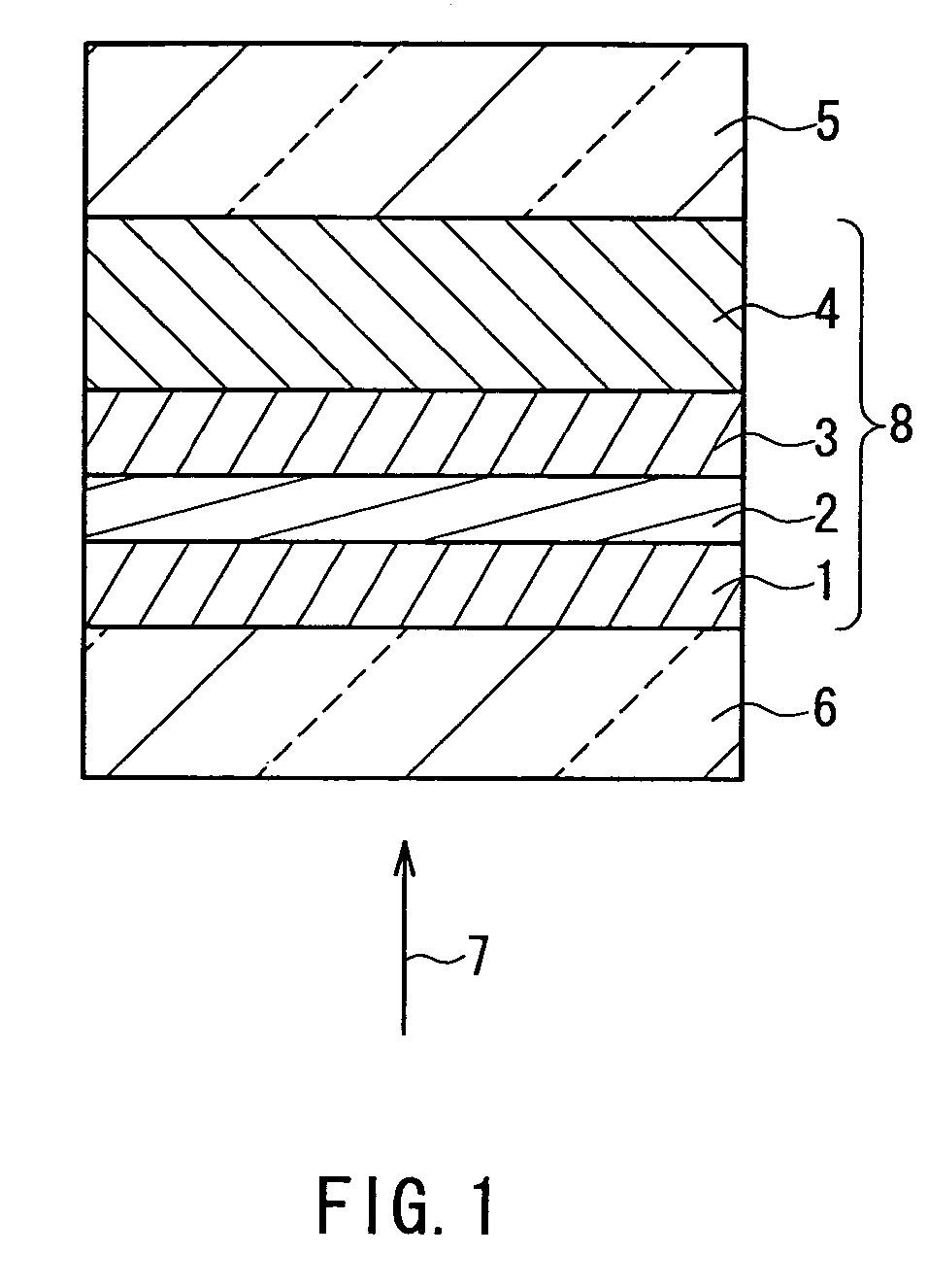
[0069]In Example 1, an optical information recording medium was produced that had a configuration shown in FIG. 1. A disc-like polycarbonate plate was used as the substrate 5. The disc-like polycarbonate plate had a thickness of 1.1 mm and a diameter of 120 mm. It had a spiral groove formed on a surface thereof. The spiral groove had a width of 0.25 μm, a pitch of 0.32 μm, and a depth of 20 nm. A mixture of 80 mol % of ZnS and 20 mol % of SiO2 (hereinafter referred to as “(ZnS)80(SiO2)20 (mol %)”, and the same applies to other mixtures) was used for the first protective layer 1. A mixture, (ZrSiO4)90(Cr2O3)10 (mol %) was used for the second protective layer 3. A mixture, Al98Cr2 (atomic %) was used for the reflective layer 4. A mixture, Te43O50Pd7 (atomic %) was used for the recording layer 2. The first protective layer 1 and the second protective layer 3 had a thickness of 6 nm and a thickness of 17 nm, respectively. The reflective layer 4 and the recording layer 2 had a t...

Example

Example 2

[0082]An optical information recording medium having a configuration shown in FIG. 5 was produced as another example. The substrate 5 shown in FIG. 5 was the same as that of the medium (1) described in Example 1. The reflective layers 104 and 204 were formed of Ag—Pd—Cu and Al—Cr, respectively. The recording layers 102 and 202 were formed of Te50O25Pd25 (atomic %) and (Te50O25Pd25)95(SiO2)5 (mol %), respectively. All the first protective layers 101 and 201 and the second protective layer 203 were formed of (ZnS)80(SiO2)20 (mol %). The second protective layer 103 was formed of (ZrSiO4)30(Cr2O3)40(LaF3)30 (mol %). The refractive index of the (ZrSiO4)30(Cr2O3)40(LaF3)30 (mol %) at the wavelength of 405 nm is 2.0, which is smaller than the refractive index of the (ZnS)80(SiO2)20 (mol %), namely 2.3. That is, the first information layer 100 employed the configuration of the information layer of the optical information recording medium according to the present invention.

[0083]Thi...

Example

Example 3

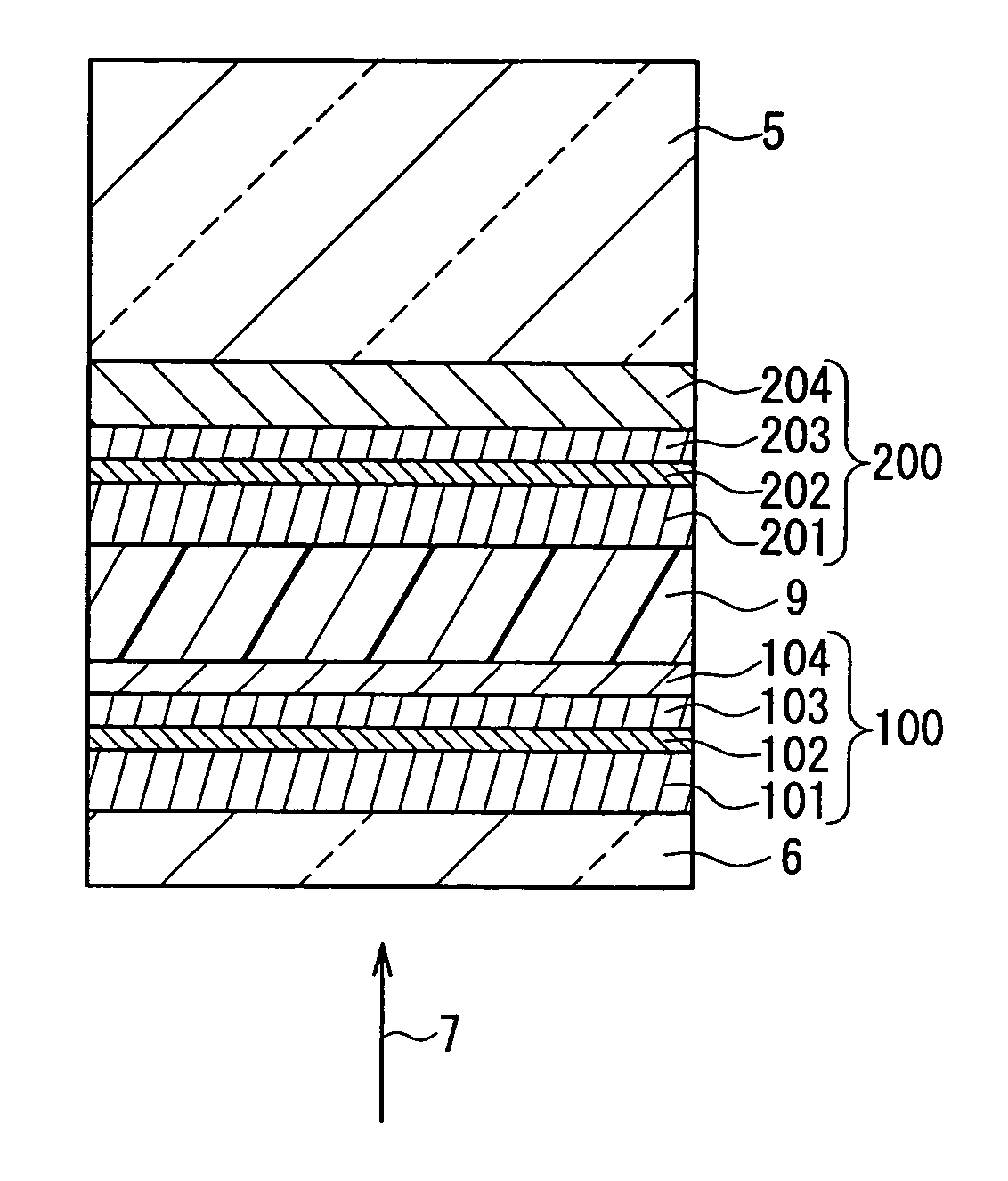
[0088]An optical information recording medium having four information layers shown in FIG. 7 was produced as another example.

[0089]First, the procedure for producing the optical information recording medium of the present example is described. The respective layers of the fourth information layer 400 were formed on the grooved surface of the substrate 5 sequentially from the reflective layer 404 to the first protective layer 401. Subsequently, an ultraviolet curable resin was applied thereto as the intermediate layer 9 and the same groove as that of the substrate 5 was formed at its surface by printing. Thereafter, the respective layers of the third information layer 300 were formed on the grooved surface of the intermediate layer 9 sequentially from the reflective layer 304 to the first protective layer 301. Then an ultraviolet curable resin was applied thereto as the intermediate layer 9 and the same groove as that of the substrate 5 was formed at its surface by printing....


PUM

PropertyMeasurementUnit
Thicknessaaaaaaaaaa
Transmittivityaaaaaaaaaa
Metallic bondaaaaaaaaaa

Abstract

The optical information recording medium of the present invention includes an information layer provided on a substrate. The information layer includes: a recording layer with respect to which information can be recorded and reproduced through irradiation with a laser beam having a predetermined wavelength; a first protective layer that is located, with respect to the recording layer, on the side to which the laser beam is incident; and a second protective layer that is located, with respect to the recording layer, on the opposite side to the side to which the laser beam is incident. The refractive index n1 of the first protective layer and the refractive index n2 of the second protective layer at the predetermined wavelength of the laser beam that is used for recording and reproduction satisfy a relationship of n2<n1.

Description

BACKGROUND OF THE INVENTION[0001]1. Field of the Invention[0002]The present invention relates generally to an optical information recording medium that allows information to be recorded and reproduced at a high density and a high speed through an optical means such as, for example, laser beam irradiation.[0003]2. Related Background Art[0004]Optical information recording media such as, for instance, magneto-optic recording media and recording media of a phase-change type, have been known as media that allow a large quantity of information to be recorded and reproduced at a high speed. In these optical information recording media, the change in optical characteristics of a recording material that is caused when the recording material is irradiated locally with a laser beam is used for recording marks. These optical information recording media have great advantages in that they permit random access as needed and have excellent portability. Hence, recently, their significance has been i...

Claims


Application Information

Patent Timeline
IPC IPC(8): H01L31/0232G11B7/00G11B7/24038G11B7/243G11B7/2433G11B7/253G11B7/2531G11B7/2533G11B7/2534G11B7/257G11B7/2578G11B7/258G11B7/2585G11B7/259G11B7/2595
CPCG11B7/24038G11B7/2578G11B7/2433G11B2007/25718G11B7/2531G11B7/2533G11B7/2534G11B7/2585G11B7/259G11B7/2595G11B2007/0013G11B2007/24304G11B2007/24306G11B2007/24308G11B2007/2431G11B2007/24312G11B2007/24314G11B2007/24316G11B2007/2432G11B2007/25706G11B2007/25708G11B2007/2571G11B2007/25711G11B2007/25713G11B2007/25715G11B2007/25716E01C5/005E01C5/18E01C2201/12E01C2201/16
Inventor UNO, MAYUMIKOJIMA, RIEYAMADA, NOBORU
Owner PANASONIC CORP
Why Eureka
Try Eureka