Eureka AIR delivers breakthrough ideas for toughest innovation challenges, trusted by R&D personnel around the world.

Display apparatus and portable device

a technology of display apparatus and portable device, which is applied in the direction of static indicating device, non-linear optics, instruments, etc., can solve the problems of increasing relatively high cost, and too large power consumption of portable device, so as to achieve the effect of further reducing power consumption

Inactive Publication Date: 2006-06-06
SHARP KK
View PDF20 Cites 16 Cited by
  • Summary
  • Abstract
  • Description
  • Claims
  • Application Information

AI Technical Summary

Benefits of technology

The present invention provides a display apparatus that reduces power consumption, increases driver output frequency, or restrains the increase in power consumption while increasing the driver output frequency. The display apparatus also reduces the size of the display means, making it suitable for use in mobile devices. A mobile device that uses this display apparatus is also provided. The display apparatus includes multiple display devices and voltage variation sections for changing the display voltage supplied to the display devices. This arrangement reduces the electricity used for charging up / down the data line, reduces the size of switching devices, and reduces the area occupied with the source driver, resulting in a smaller and more energy-efficient display apparatus.

Problems solved by technology

The portable devices have become multifunctional so that the power consumption thereof has become increased.
Apart from the relatively high cost, the reason of the poor demand for the TFT liquid crystal panel is mainly considered that the power consumption thereof is too large to be adopted as the display means of the portable device.
Liquid crystal panels basically consume small amounts of electric power compared to conventional CRT display apparatuses.
However, as a kind of the liquid crystal panel, the TFT liquid crystal panel can realize high-definition displaying but requires relatively large amounts of electric power, so as to be inadequate for the display means of the portable device.
More specifically, conventional TFT liquid crystal panels are arranged such that the data written in all pixels of the TFT liquid crystal panel are updated in every frame time to realize displaying without flicker, and this increases the power consumption.
In this case, however, the arrangement of the circuit is so complicated that the drive circuit (especially a source driver) of the TFT liquid crystal panel requires a larger area.
However, the first and second objectives are not fully achieved with the aforementioned techniques, when the TFT liquid crystal panel is used as the display means of the portable device.
Thus on the occasion of generating the intermediate voltage (i.e. a display voltage), a lot of electricity is consumed.
However, in this arrangement, corresponding to the time ratio grayscale display, a frequency supplied from the D / A conversion circuit is multiplied by a factor of (m−n) and in proportion to this increase of the frequency, the power consumption of wire capacitance increases.
However, in this case, also a frequency supplied from the buffer is multiplied by a factor of m (bits) so that the power consumption of wire capacitance increases.
The increase of the frequency in accordance with the time ratio grayscale gives rise to the increase of the power consumption, and this hinders the reduction of the power consumption.
However, no matter which method is adopted, the arrangement of the liquid crystal panel has to be significantly changed, and hence the increase of the costs, the alteration of the manufacturing process, etc. are inevitable so that adopting the aforementioned methods is considered to be unrealistic.
Consequently, both the techniques (1) and (2) cannot achieve the objectives (1) and (3) adequately.
Moreover, even though the D / A conversion circuit can be arranged without complicacy, the increase of the area occupied with the D / A conversion circuit cannot be avoided adequately.
Thus the area occupied with the source driver cannot be reduced and hence the second objective cannot be achieved sufficiently by this technique.
In this organic EL display, however, the problems related to the D / A conversion circuit and the source driver also occur, as in the case of the liquid crystal panel.

Method used


Image

  • Display apparatus and portable device
  • Display apparatus and portable device
  • Display apparatus and portable device

Examples


embodiment 1

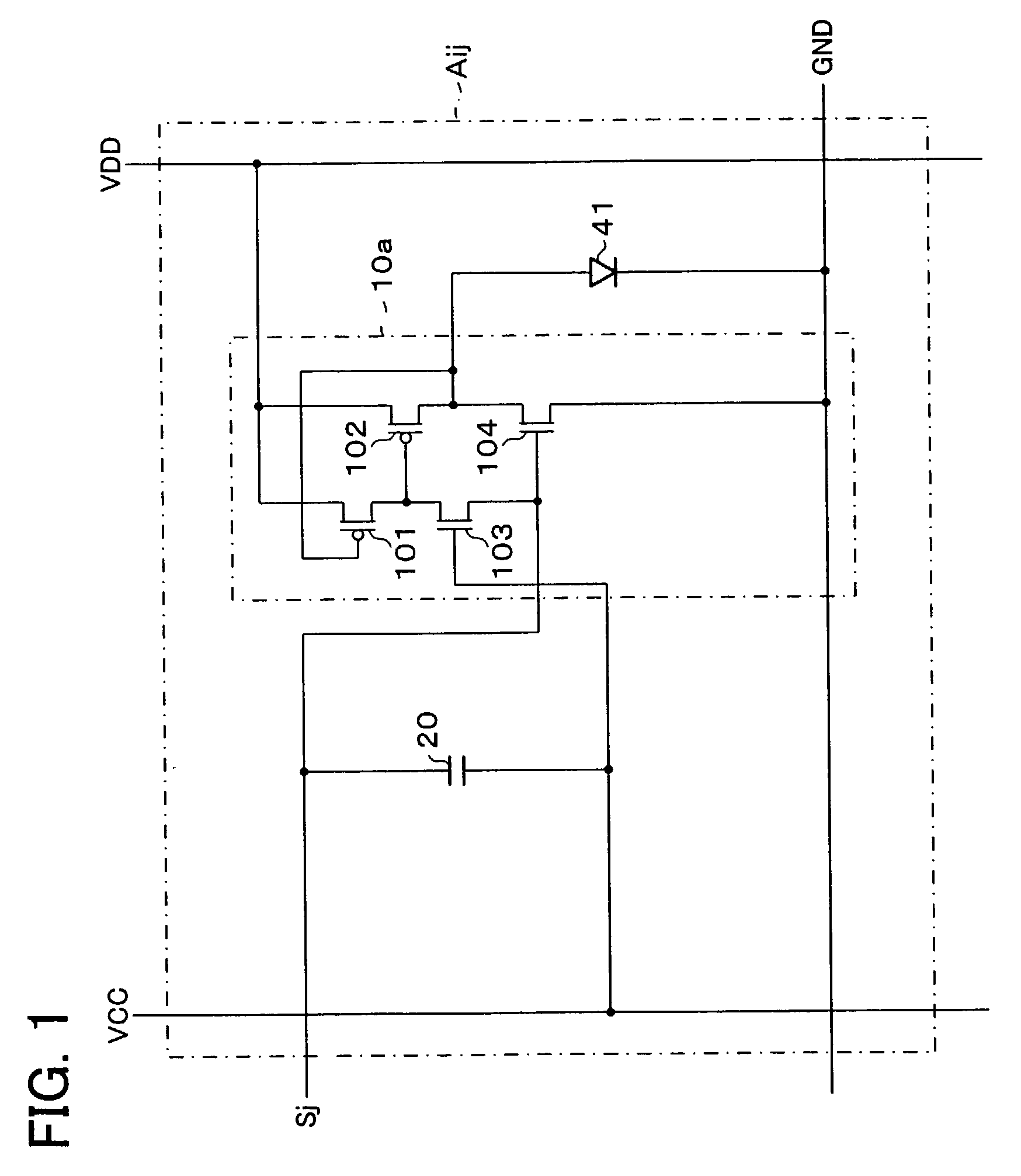
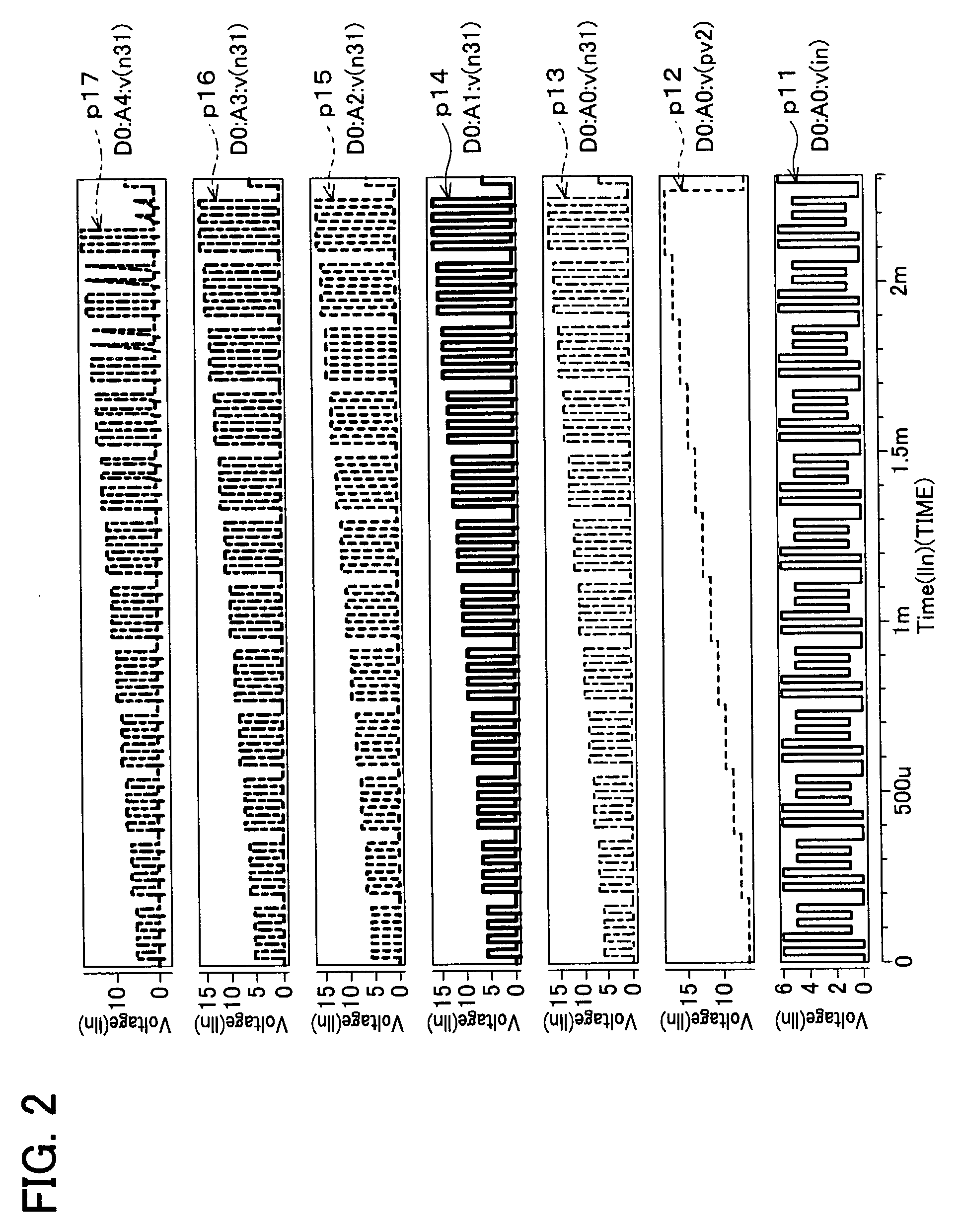
[0057]The following description will discuss a first embodiment in accordance with the present invention in reference to FIGS. 1 and 2. It is noted that the present invention is not limited to this embodiment.

[0058]A display apparatus in accordance with the present invention, in which a plurality of display devices is provided in a display area, includes voltage variation means between an output terminal of a drive circuit and the respective display device.

[0059]More specifically, as FIG. 1 shows, for instance, a single pixel Aij is arranged such that a single voltage variation section (voltage variation means) 10a is provided so as to correspond to an organic EL device 41 which is the display device.

[0060]In the arrangement in FIG. 1, an output terminal of a source driver (drive circuit) which is not illustrated is connected to a data line (first line) Sj, the data line Sj is connected to a capacitor (voltage keeping section) 20, and the voltage variation section 10a is connected b...

embodiment 2

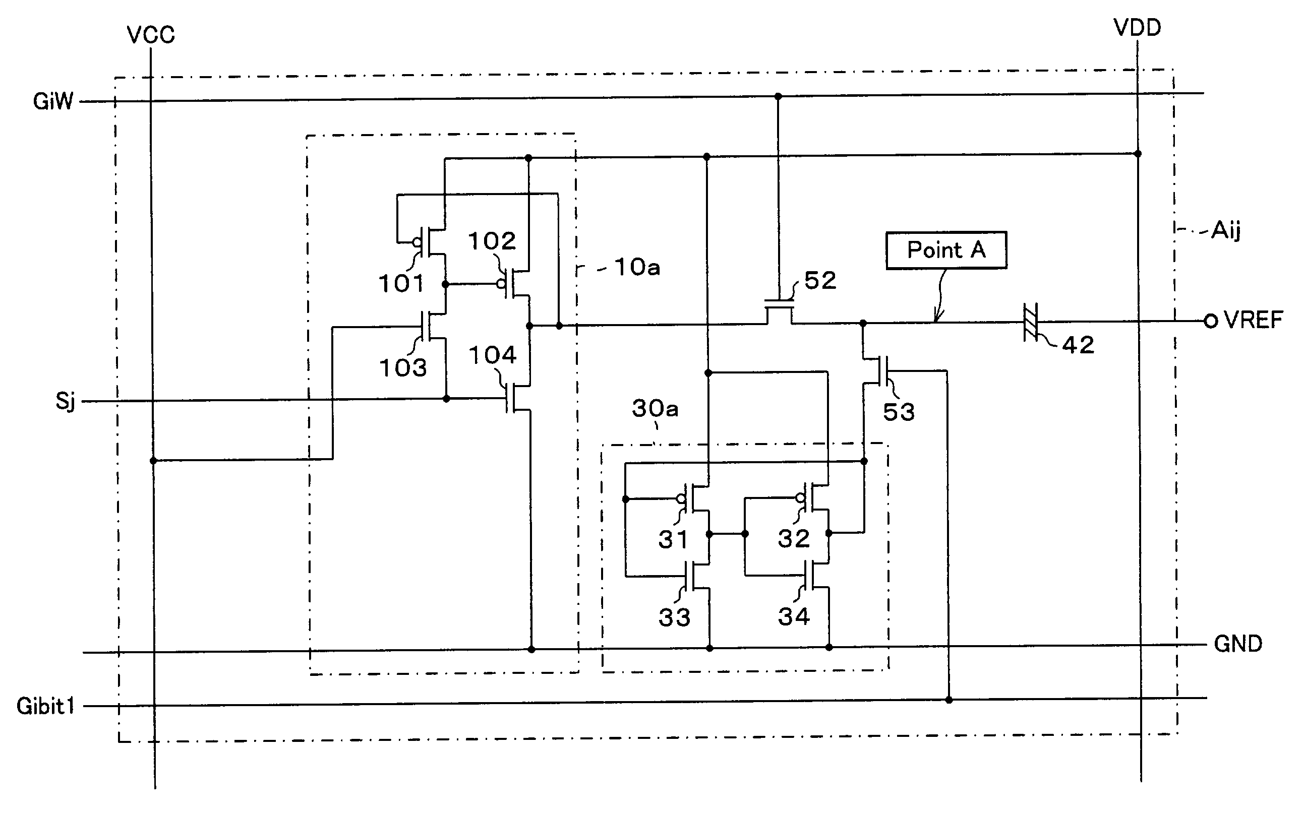
[0104]The following description will discuss a second embodiment of the present invention with reference to FIGS. 3 and 4. By the way, it is noted that the present invention is not particularly limited to this embodiment, and members having the same functions as those described in first embodiment are given the same numbers, so that the descriptions are omitted for the sake of convenience.

[0105]the first embodiment is arranged so that the source driver may include the D / A conversion circuit as long as the voltage variation section is an operational amplifier, and it is possible to supply a multi-grayscale voltage to the display device. However, it is difficult to form the operational amplifier corresponding one to one to the display device, and thus the present invention is preferably arranged such that the image data supplied to the display device is binary image data.

[0106]In this case, as FIG. 3 shows, a display apparatus in accordance with the present invention includes storage ...

embodiment 3

[0153]The following description will discuss a third embodiment of the present invention with reference to FIGS. 5 through 8. By the way, it is noted that the present invention is not particularly limited to this embodiment, and members having the same functions as those described in embodiments 1 and 2 are given the same numbers, so that the descriptions are omitted for the sake of convenience.

[0154]Although embodiments 1 and 2 exemplified such the case as the output terminal of the source driver corresponds one to one to the display device, the present invention is not particularly limited to this arrangement, so that one output terminal of the source driver may correspond to a plurality of the display devices. This arrangement makes it possible to increase the load-carrying capacity from the output terminal of the source driver to the display devices, compared to the one-to-one correspondence, so that the effect of the present invention to reduce the power consumption can be furt...


PUM

PropertyMeasurementUnit
voltageaaaaaaaaaa
voltageaaaaaaaaaa
voltageaaaaaaaaaa

Abstract

A display apparatus is arranged such that each of a plurality of pixels formed on a display area has, for instance, an organic EL device as a display device, and each of the organic EL devices has a voltage variation section which can change the value of a display voltage supplied to each of the organic EL devices. Moreover, the display apparatus preferably includes voltage keeping sections for keeping the input voltage of the voltage variation sections and storage sections for storing image data. On this account, it is possible to further reduce the power consumption of the display apparatus and downsize the display apparatus as display means, so that the display apparatus can be suitably adopted as display means of a mobile device.

Description

FIELD OF THE INVENTION[0001]The present invention relates to (i) a thin display apparatus which is preferably realized as a liquid crystal display apparatus or an organic EL (Electro Luminescence) display apparatus and a driving method thereof, and (ii) a portable device or a time ratio grayscale display apparatus including the above-mentioned display apparatus, and more particularly to a low-power-consumption display apparatus suitable for display means of the portable device or that of the time division display apparatus and a driving method thereof.BACKGROUND OF THE INVENTION[0002]There has been a great deal of interest in developing a thin display apparatus such as a liquid crystal display apparatus, an organic EL (Electro Luminescence) display apparatus, and an FED (Field Emission Device) display apparatus. Among them, the liquid crystal display apparatus and a thin EL display apparatus have particularly attracted attention as a display apparatus for mobile phones and portable ...

Claims


Application Information

Patent Timeline
Patent Type & Authority Patents(United States)
IPC IPC(8): G09G3/30G02F1/133G09G3/20G09G3/32G09G3/36H01L51/50
CPCG09G3/3258G09G3/3648G09G3/3685G09G2300/0408G09G2330/021G09G2300/0809G09G2300/0833G09G2300/0857G09G2300/0417G02F1/133
Inventor NUMAO, TAKAJI
Owner SHARP KK
Why Eureka
Eureka Blog
Learn More