
Systems and methods for constructing an image having an extended depth of field

a technology of depth of field and image processing system, which is applied in image enhancement, image data processing, instruments, etc., to achieve the effect of preserving detail, balancing efficacy and throughput time, and reliable results

Inactive Publication Date: 2006-06-06
MITUTOYO CORP
View PDF7 Cites 52 Cited by
  • Summary
  • Abstract
  • Description
  • Claims
  • Application Information

AI Technical Summary

Benefits of technology

[0012]Thus, considering that a composite image is successful to the extent that the composite image retains all useful information, does not contain artifacts, and looks natural, and furthermore considering the commercial value and convenience of rapid computation, and furthermore considering the need for robust and reliable results on variety of unpredictable workpiece features and configurations, there is a need for an improved, commercially-appealing solution that balances efficacy against throughput time and provides a high-resolution well-focused image of a small portion of a three-dimensional object while also allowing the user to clearly observe or record the area surrounding that small portion of the three-dimensional object. This problem is particularly significant in automated machine vision systems used for microscopic inspection and measurement. In such systems, there is a need for a composite image construction method that is relatively fast, preserves detail, provides robust results on variety of unpredictable workpiece features and configurations, and that tends to suppress or reduce out-of-focus artifacts.
[0013]This invention provides systems and methods that construct a desirable composite image having an extended depth of focus in a relatively short time, and preserves the image detail present in a plurality of source images.
[0015]This invention further provides systems and methods that are readily adaptable to construct a desirable composite image even more reliably, robustly, and in an even shorter time, when certain workpiece features are predictable.
[0018]In various exemplary embodiments, the composite image is generated hierarchically, in that the determined edges or boundaries are given priority in the composite image regardless of whether an apparently well-focused surface portion is identified at the same spatial location as an edge or boundary. This tends to suppress artifacts in the composite image in the vicinity of boundaries and edges.
[0019]In various other exemplary embodiments of the systems and methods according to this invention, additional buffer zones are established immediately adjacent to determined edges or boundaries. The composite image generation in these buffer zones suppresses artifacts which might otherwise be created by out-of-focus edges “bleeding over into surface regions” in some source images and producing anomalous results during the surface analysis.
[0021]In contrast to the previously discussed conventional methods, in the various exemplary embodiments of the systems and methods according to this invention, the composite image can be constructed relatively quickly while preserving detail in the composite image. The resulting composite images can be constructed robustly in view of a variety of unpredictable workpiece features and configurations, while out-of-focus artifacts in the resulting composite images tend to be suppressed or reduced.

Problems solved by technology

This problem is particularly significant in automated machine vision systems used for microscopic inspection and measurement.

Method used


Image

  • Systems and methods for constructing an image having an extended depth of field
  • Systems and methods for constructing an image having an extended depth of field
  • Systems and methods for constructing an image having an extended depth of field

Examples


Embodiment Construction

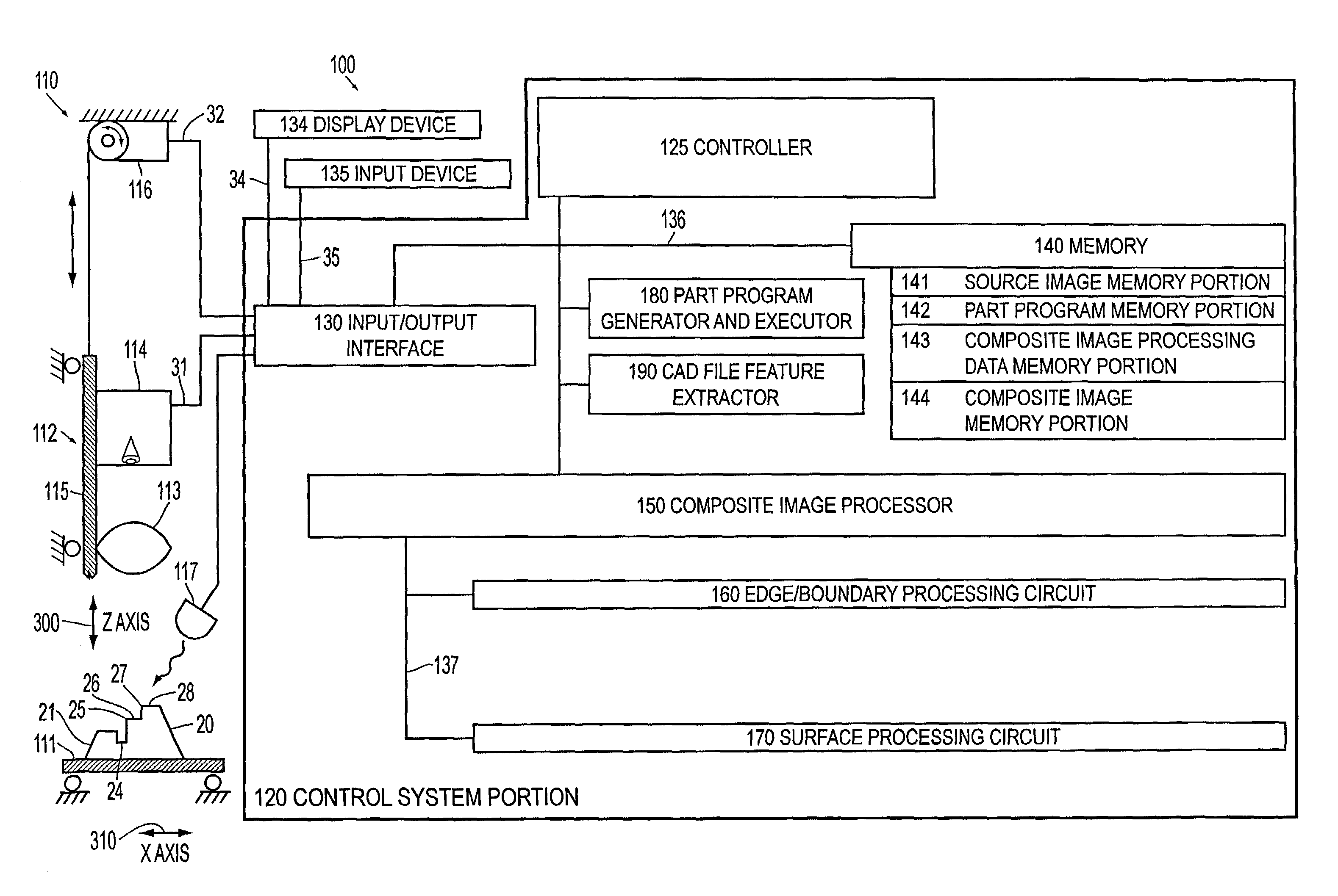
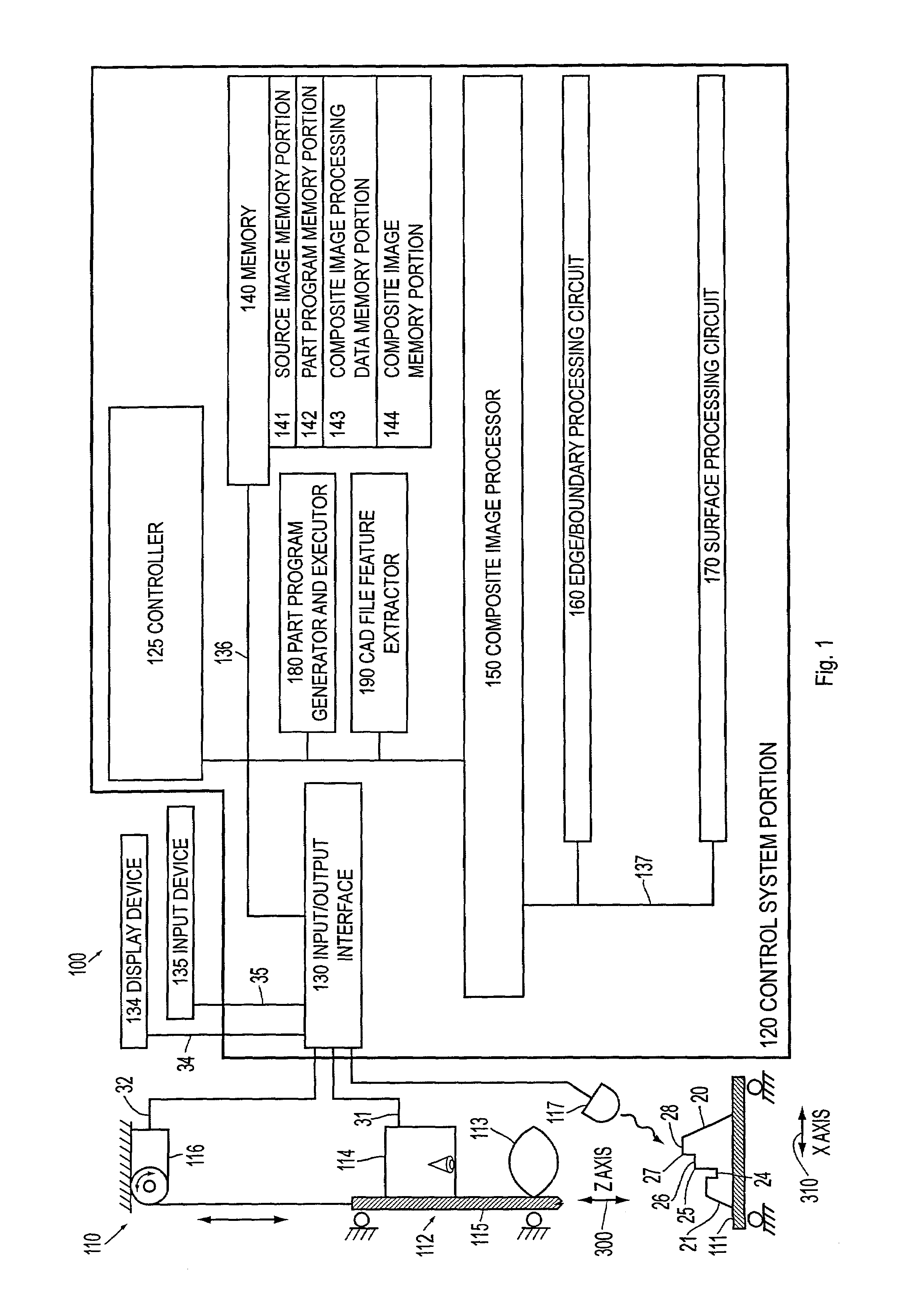
[0037]For simplicity and clarification, the operating principles, and design factors of various exemplary embodiments of the systems and methods according to this invention are explained with reference to one exemplary embodiment of a vision system 100, as shown in FIG. 1. The basic explanation of the operation of the vision system shown in FIG. 1 is applicable for the understanding and design of any vision system that incorporates the systems and / or methods of this invention. Although the systems and methods of this invention are described in conjunction with this specific vision system 100, the systems and methods according to this invention can be used with any other known or later-developed vision system.

[0038]FIG. 1 shows a vision system 100. As shown in FIG. 1, the vision system 100 includes a vision system components portion 110 and a control system portion 120. The control system portion 120 includes elements, including a composite image processor 150, which constitute a com...


PUM


Abstract

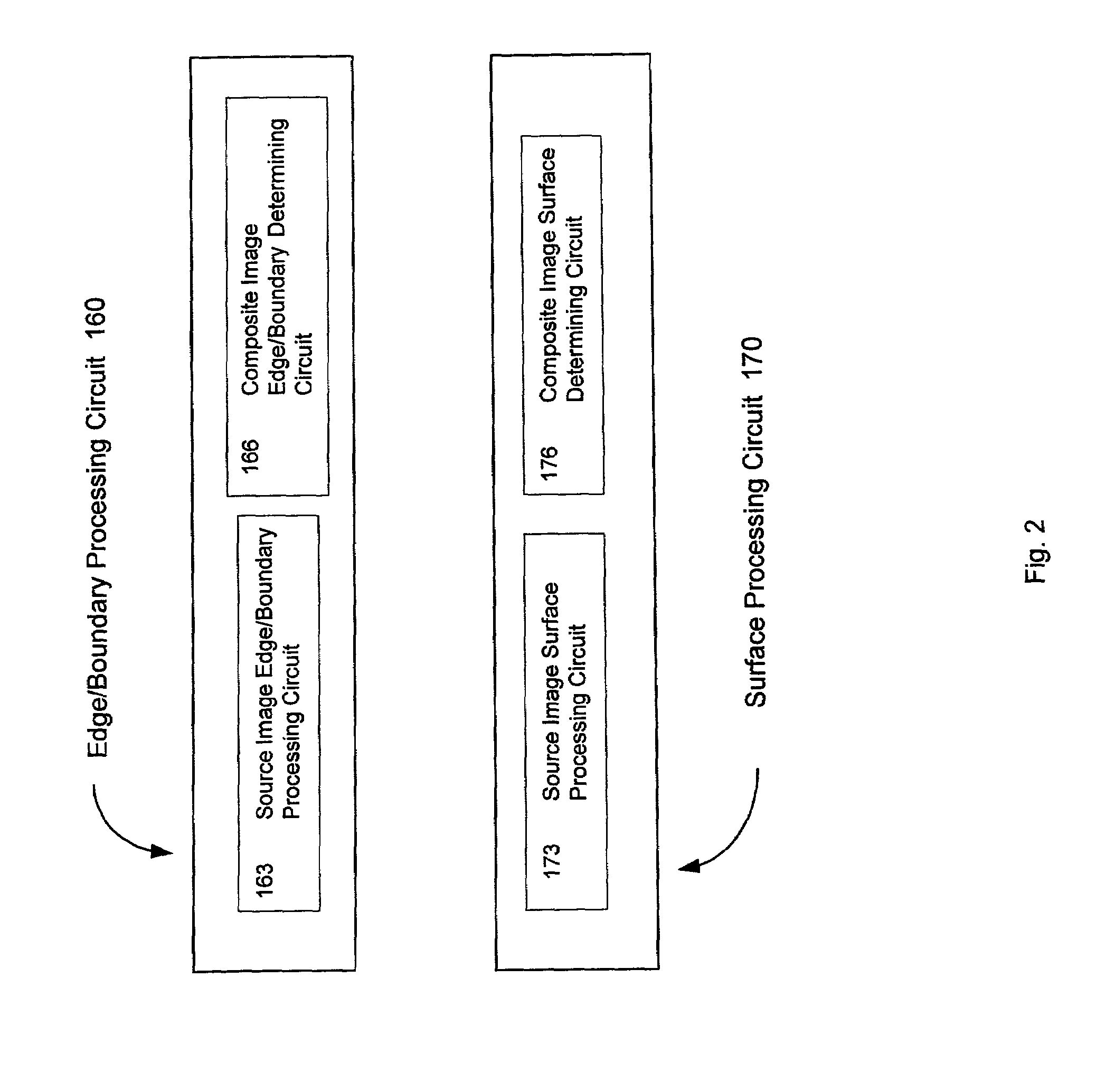
Systems and methods are provided for constructing a composite image having an extended depth of focus from a plurality of spatially congruent source images of lesser depth of focus. The systems and methods are relatively fast, preserve detail, provide robust results on a variety of unpredictable workpiece features and configurations, and tend to suppress or reduce out-of-focus artifacts. The composite image is constructed by edge and / or boundary analysis to identify well-focused edges or boundaries in the source images. Each particular edge or boundary in the composite image is determined based on the source image containing the best-focused instance of each particular edge or boundary. The composite image is constructed outside of the previously constructed portions by surface analysis to identify well-focused surfaces in the source images, Each particular surface portion in the composite image is determined based on the source image with the best-focused instance of each particular surface portion.

Description

BACKGROUND OF THE INVENTION[0001]1. Field of Invention[0002]This invention relates to image-processing systems and methods usable to construct a composite image.[0003]2. Description of Related Art[0004]High resolution machine vision systems, and especially microscopic machine vision systems, often provide a high-resolution, well-focused image of a small portion of a three-dimensional object. However, this is accomplished at the expense of the depth of field, also called the depth of focus, of the surrounding overall image. However, in some machine vision system applications, it is useful both to make high-resolution well-focused microscopic examination and / or record of a small portion of an object and to clearly observe or record the surrounding overall image.[0005]Methods are known for combining, or fusing, separately focused images of a three-dimensional scene or object to accomplish this useful goal. For example, U.S. Pat. No. 4,141,032 to Haeusler discloses focusing through an o...

Claims


Application Information

Patent Timeline
IPC IPC(8): G06K9/42G01B11/00G06T1/00G06T5/50
CPCG06T5/50
Inventor SILBER, ANDREW DAVID
Owner MITUTOYO CORP
Learn More