Use of multi-layer thin films as stress sensors

a multi-layer thin film and stress sensor technology, applied in the field of tunneling magnetoresistive devices, can solve the problems of capacitive sensors providing erroneous readings, inherently subject measurement of spacing, adverse effects of most of these sensors, etc., and achieve the effect of reducing the magnetic moment of the free ferromagnetic layer and reducing the magnetic moment of the pinned ferromagnetic layer

Inactive Publication Date: 2006-06-13
LENOVO PC INT
View PDF14 Cites 26 Cited by
  • Summary
  • Abstract
  • Description
  • Claims
  • Application Information

AI Technical Summary

Benefits of technology

[0010]It is another object of the current invention to magnetically pin one ferromagnetic layer while allowing the other ferromagnetic layer to rotate freely under the action of an externally applied stress.
[0011]It is another object of the current invention to reduce the magnetic moment of the free ferromagnetic layer by forming a composite trilayer stack containing a ferromagnetic layer, a spacer layer, and another antif

Problems solved by technology

The measurement of spacing is inherently subject to several distortion effects: since the height difference between the ridges and valleys is only of the order of 50 microns, any parameter which affects the spacing between the finger and the sensor will affect the measurement.
In addition, most of these sensors are adversely affected by ambient temperature at the time of sensing, as well as electrostatic discharge (ESD).
Under very hot or very cold conditions,

Method used


Image

  • Use of multi-layer thin films as stress sensors
  • Use of multi-layer thin films as stress sensors
  • Use of multi-layer thin films as stress sensors

Examples


Embodiment Construction

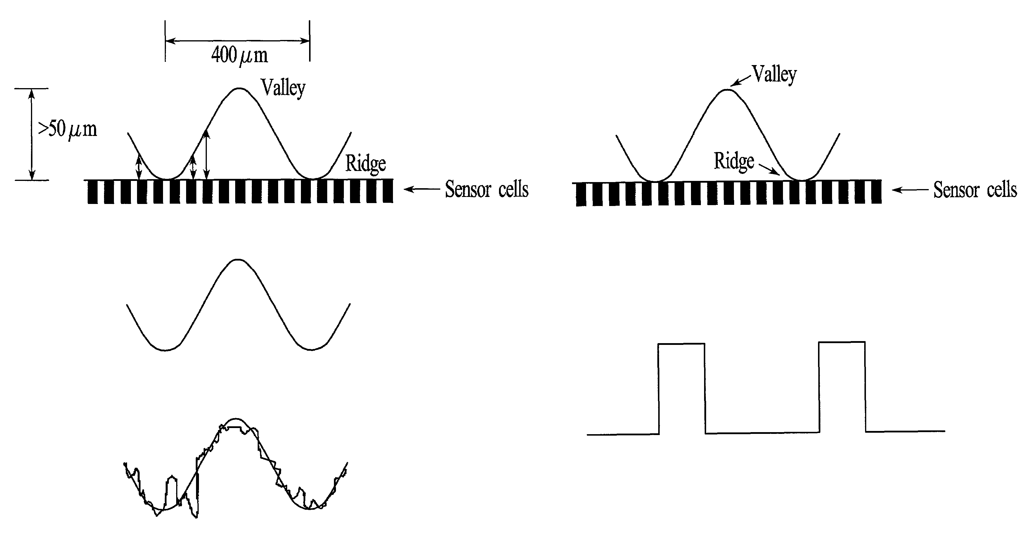
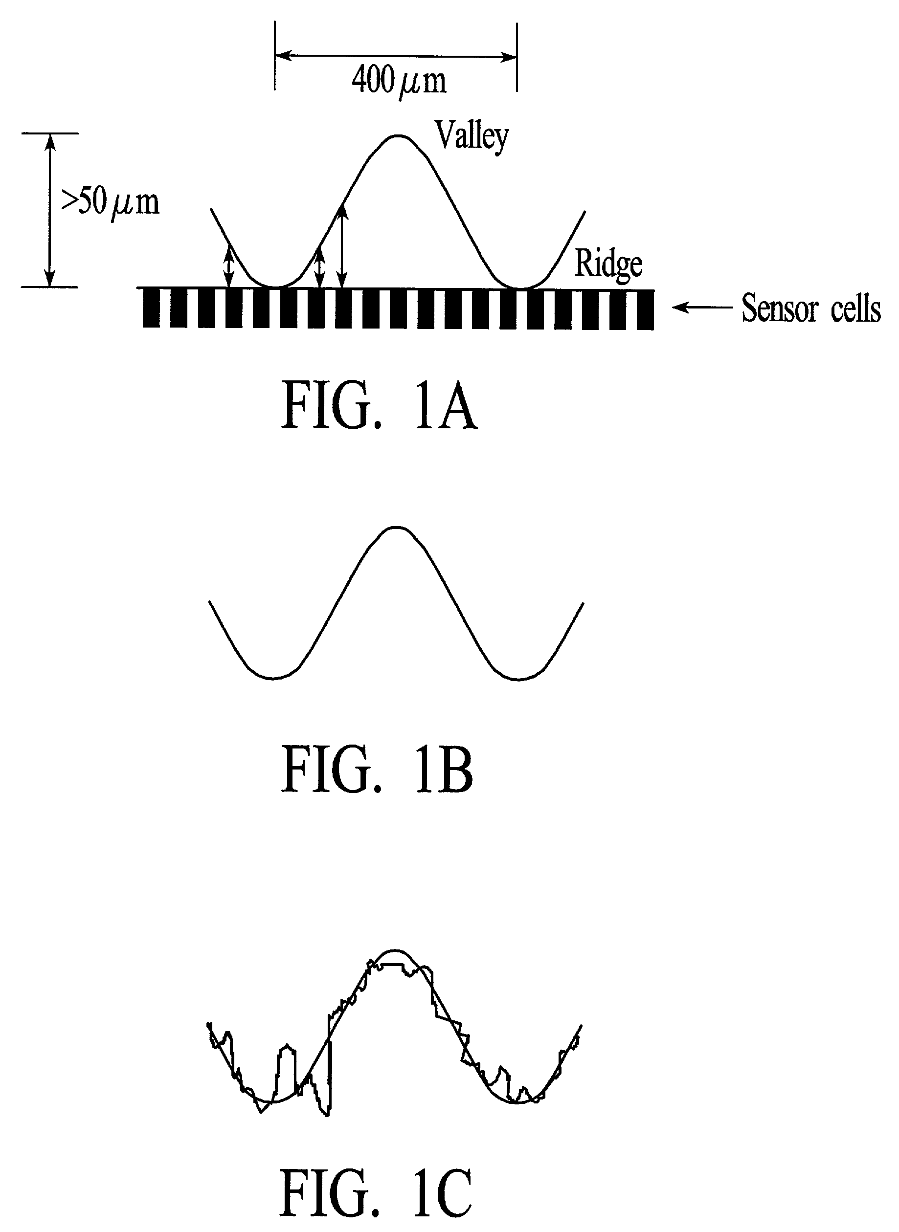
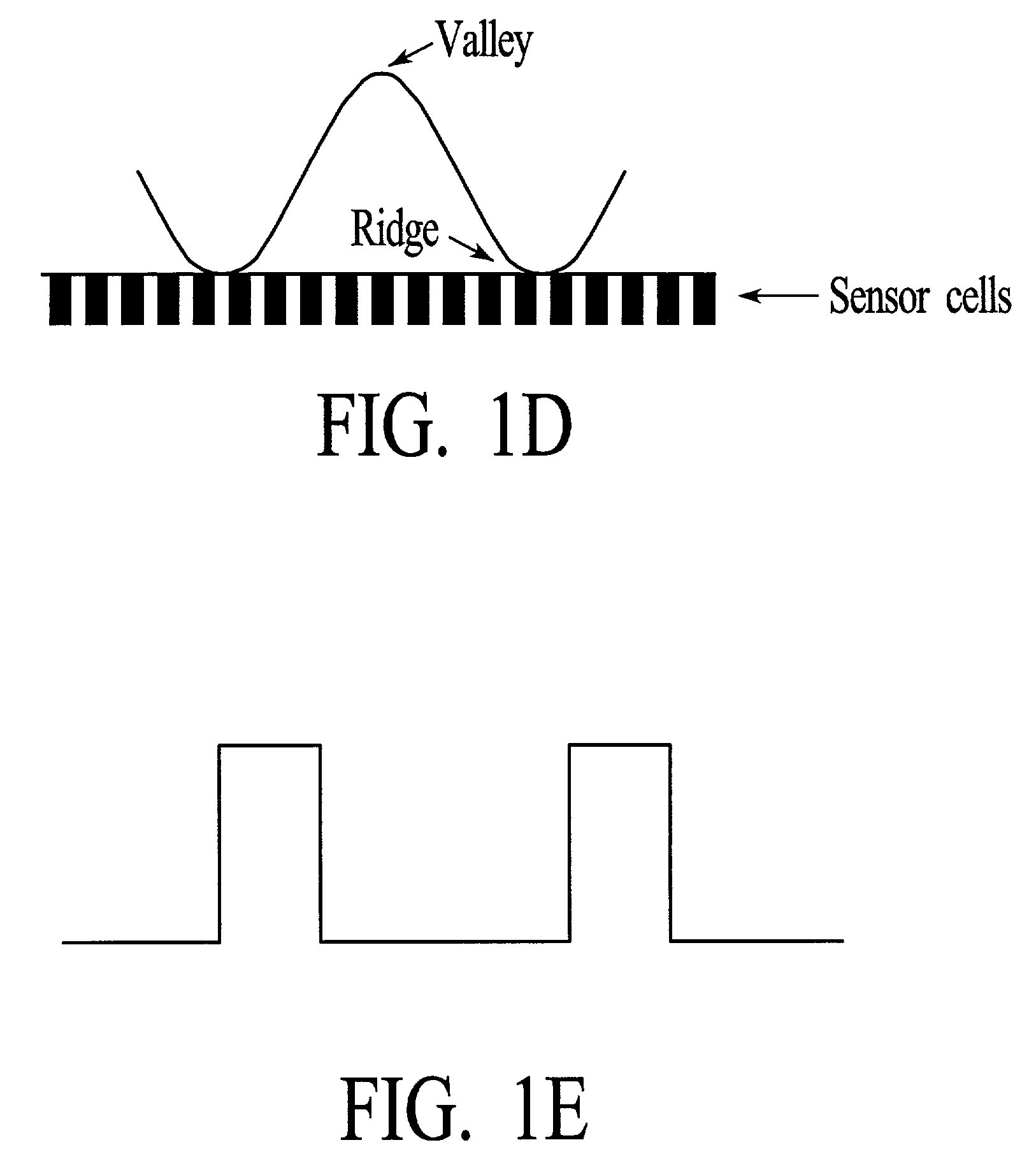
[0035]The working principle of TMR has certain similarities to that of GMR, since in both TMR sensors (as described herein) and GMR sensors, a change in applied pressure will cause a rotation of the magnetization associated with the device, and a corresponding change in resistance, which can be sensed. Further, in both devices, there is a stack of layers, in which the innermost and outermost layers are made of ferromagnetic materials. Despite those similarities, implementation of a TMR device is very different from implementation of a GMR device. In particular, this is due to the fact that the layer between the inner and outer ferromagnetic layers is an insulating, rather than a conducting material, and the electrical current flows perpendicular to the plane of the layers, rather than in the plane of the layers.

[0036]As a result of these differences, the following observations have been noted by the present inventors, which lead to the conclusion that a TMR device can have advantage...


PUM


Abstract

The present invention provides a pressure sensing device that includes at least one TMR sensor, and preferably an array of TMR sensors, with each TMR sensor having an insulating spacer layer interposed between a pinned and a free ferromagnetic layer. In an unbiased state, the magnetization vector of each of the ferromagnetic layers is preferably parallel to each other. Upon application of a small voltage, the magnetization vectors remain unchanged. Upon application of stress, the magnetization vector of the free magnetic layer will rotate, thus causing a corresponding and proportionally related change in the resistance of the sensor. This change in resistance can be sensed and used to calculate the stress applied thereto.

Description

FIELD OF THE INVENTION[0001]The present invention relates to Tunneling MagnetoResistive (TMR) devices in conjunction with micromachined beams to measure stresses with high sensitivity, and methods of making and using the same.BACKGROUND OF THE INVENTION[0002]Historically, fingerprint image-capture devices have used optical-based sensors or capacitance-based sensors. With reference to the specific example of a fingerprint, optical sensors use a light source, lenses and a prism to image the “ridges” and valleys on the fingerprint, based on differences in the reflected light from the features. The conventional capacitance sensor uses semiconductor type processing to fabricate a two-dimensional array of capacitors. The individual sensors form one plate of the parallel plate capacitor, while the finger itself, when placed on the array, acts as the second plate. Upon contact with the array of sensors, the individual distance from each sensor to the skin is measured using capacitive techni...

Claims


Application Information

Patent Timeline
IPC IPC(8): G01D7/00G01L1/12G06K9/00
CPCG01L1/125G06K9/0002G06V40/1306
Inventor PRAKASH, SHIVAGANAPATHI, SRINIVASAN K.GLUCK, RANDOLPH S.HOVEY, STEVEN H.
Owner LENOVO PC INT
Why Eureka
Try Eureka