Methods and apparatus for bypassing arterial obstructions and/or performing other transvascular procedures

a technology of bypassing and occlusion of arterial walls, applied in the field of methods and equipment, can solve the problems of inability to carry out coronary artery bypass surgery, inability to carry out surgery, inability to carry out surgery, etc., and achieve the effect of enhancing tissue perfusion

Inactive Publication Date: 2006-06-13
MEDTRONIC VASCULAR INC
View PDF92 Cites 165 Cited by
  • Summary
  • Abstract
  • Description
  • Claims
  • Application Information

AI Technical Summary

Benefits of technology

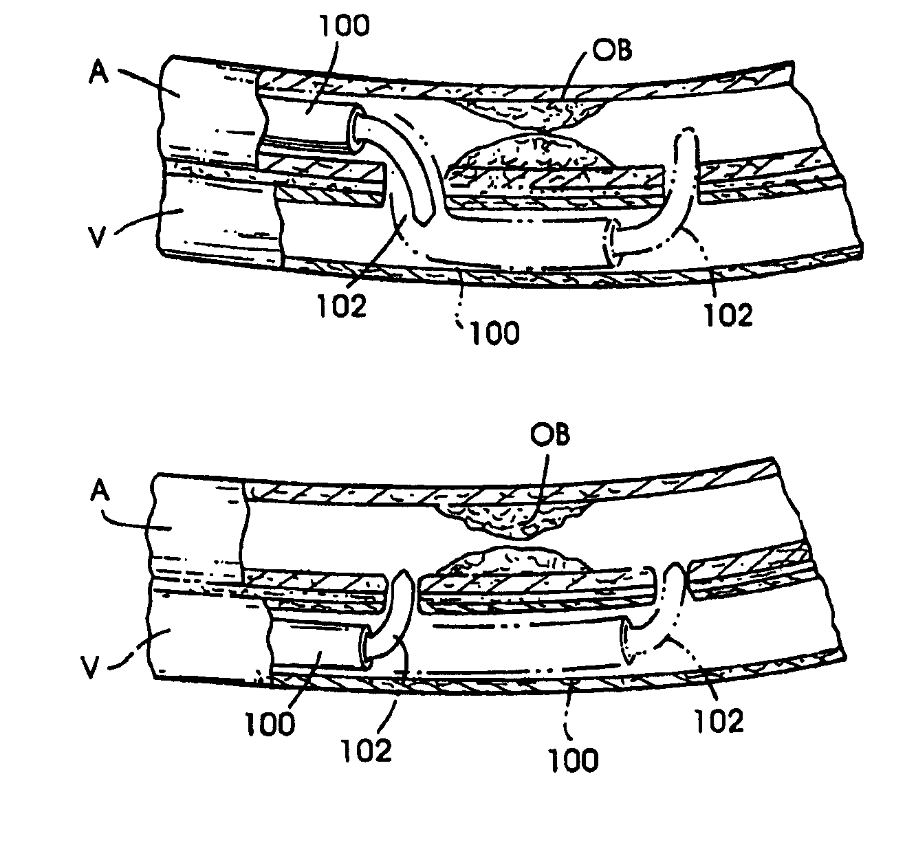
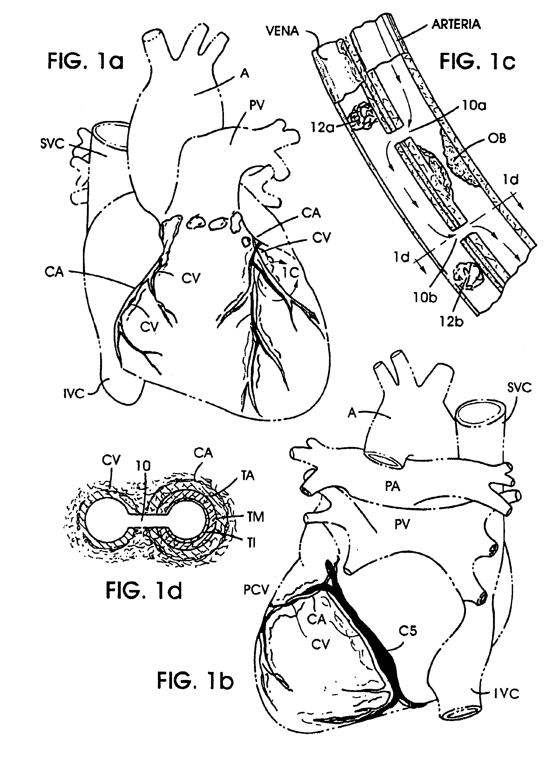
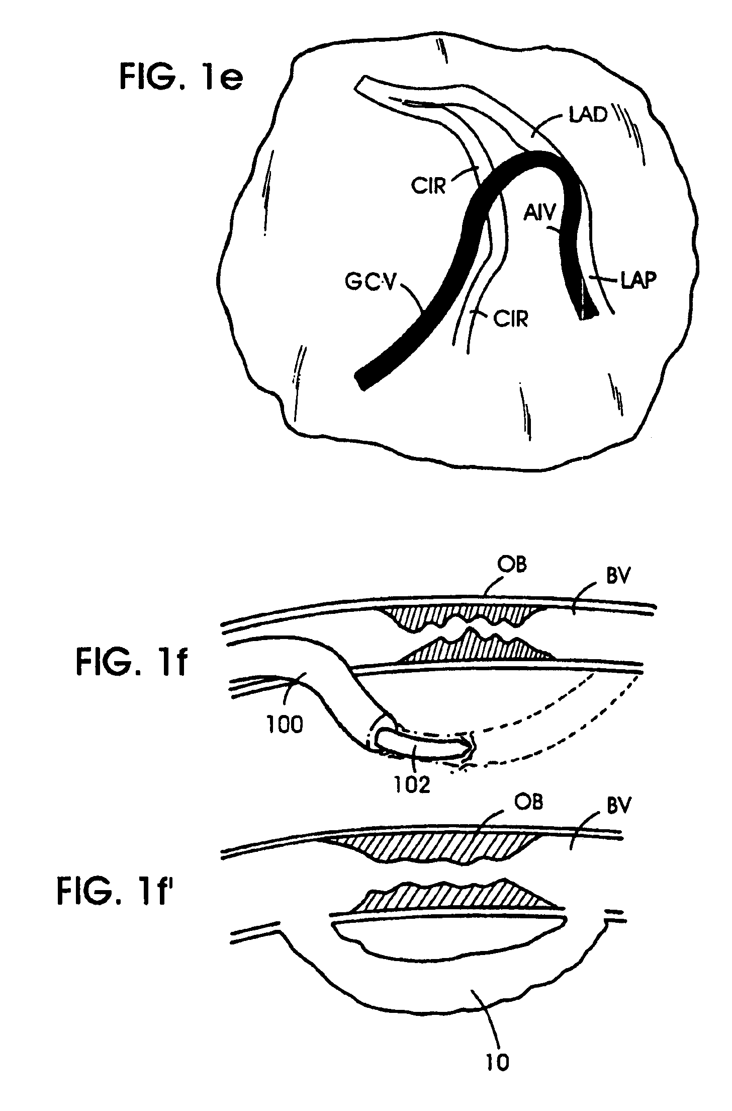
[0022]The revascularization methods of the present invention generally comprise the formation of one or more extravascular passageways between blood vessels, different locations on the same blood vessel, or a blood vessel and another blood-containing anatomical structure (e.g., chamber of the heart), such that blood will flow through such passageway(s). In many applications of the invention, it will be desirable for oxygenated blood (i.e., blood which has a pO2 greater than 50) to...

Problems solved by technology

Such deposits of atherosclerotic plaque tend to fully or partially block the flow of blood through the affected coronary arteries, and if untreated can result in myocardial ischemia, infarction and death.
Such traditional coronary artery bypass surgery is expensive, extremely invasive, and is associated with significant operative and preoperative complications.
However, balloon angioplasty procedures of this type may be associated with a significant incidence of restenosis at the angioplasty site.
Furthermore, these ablative procedures may, in some cases at least, be confounded by the need to meticulously contain and remove dislodged or severed fragments of the obstructive matter, in order to prevent such fragments of obstructive matter from escaping into the patient's circulatory system.
However, endoscopic surgical procedures of this type typically require a great deal of operator skill and training.
However, those thoracoscopic procedures which purport to be useable without cardiopulmonary bypass and heart stoppage are relatively complex to perform and typically require temporary clamp...

Method used


Image

  • Methods and apparatus for bypassing arterial obstructions and/or performing other transvascular procedures
  • Methods and apparatus for bypassing arterial obstructions and/or performing other transvascular procedures
  • Methods and apparatus for bypassing arterial obstructions and/or performing other transvascular procedures

Examples


first embodiment

[0252]FIGS. 7a and 7a′ show a tissue-penetrating element 102a. This embodiment of the tissue penetrating element 102a comprises an elongate, pliable needle formed of a pliable material such as polyimide tubing of the type availa ble commercially from MicroLumen, Inc., Tampa, Fla., and having a sharpened, beveled distal tip 300 formed thereon. An optional lumen 302 may extend longitudinally through the penetrating element 102a. A pre-bent, resilient member 304 is positioned longitudinally within the tissue-penetrating element 102a, or alternatively a pull wire.

[0253]When the element 102a is retracted within the lumen of the passageway-forming catheter 100, the resilient spine member 304a will be caused to assume a substantially straight or minimally bent configuration which conforms to the configuration of the catheter lumen and allows the tissue-penetrating element 102a to be fully retracted within the catheter lumen. However, when the tissue-penetrating element is exposed or advanc...

third embodiment

[0271]FIG. 8c shows a passageway modifying apparatus 500c which comprises an elongate tubular member having an annular, sharpened distal cutting tip 512 which is similar to the distal cutting tip 502 of the embodiment shown hereabove in FIG. 8a, W but which is further adapted to emit energy (e.g, heat, vibration, laser light, etc.). In this embodiment of the apparatus 500c, an energy transition wire or member 514 extends through the tubular proximal portion of the apparatus 500c and is connected to the annular distal cutting tip 512 so as to transmit electrical energy, ultrasonic vibration, or any other suitable form of energy to the distal tip 512, to facilitate advancement of the distal tip 512 to the desired blood vessel wall or other extravascular tissue. The hollow lumen 504 formed through the apparatus 500c permits that apparatus 500c to be advanced over a guide wire which has been positioned within the initially formed passageway or tract created by the tissue-penetrating mem...

fourth embodiment

[0272]FIG. 8d shows a passageway modifying apparatus 500d comprising an elongate tubular catheter 516 having a hollow lumen 504d extending longitudinally therethrough and an annular balloon 518 mounted on the outer surface thereof. A separate balloon infla tion lumen (not shown) will extend through a proximal portion of the catheter 516 to permit infla tion fluid to be injected into or withdrawn from the interior of the balloon 518. This embodiment of the passageway modifying apparatus 500d may be advanced over a guide wire GW which has been positioned within the initial passageway or tract created by the tissue-penetrating element, until the deflated balloon 518 is positioned within such initially created passageway or tract. Thereafter, the balloon 518 may be inflated to dilate or stretch the initially formed passageway or tract, to provide a modified extravascular passageway 10 having the desired diameter and / or configuration.


PUM


Abstract

Methods, devices, and systems for a) revascularization and/or b) performing other medical procedures at vascular or non-vascular intracorporeal locations within a mammalian body. The methods generally comprise the formation of at least one extravascular passageway from a blood vessel to a vascular or non-vascular target location. In the revascularization methods the extravascular passageway is utilized for blood flow. In the medical procedure methods the extravascular passageway is utilized as a conduit for accessing or performing procedures at the vascular or non-vascular target location. Also disclosed are catheter devices and systems which are useable to form the extravascular passageways of the invention, as well as apparatus for modifying, maintaining and/or closing such extravascular passageways.

Description

RELATED APPLICATIONS[0001]This patent application is a continuation of application Ser. No. 08 / 730,327 filed on Oct. 11, 1996, now U.S Pat. No. 6,190,353.FIELD OF THE INVENTION[0002]The present invention pertains generally to medical methods, devices, and systems, and more particularly to methods, devices, and systems for a) revasculariation and / or b) performing medical procedures at vascular or non-vascular intracorporeal locations within a mammalian body.BACKGROUND OF THE INVENTIONA. Background Relating to Revascularization Procedures[0003]In modern medical practice, it is often desirable to bypass segments of artery which have become obstructed, diseased or injured. The typical surgical procedures used for bypassing of obstructed, diseased or injured segments of blood vessel require open surgical exposure of the artery, and the attachment (e.g., suturing) of a tubular graft (e.g., homograft, xenograft, allograft, prosthetic or bioprosthetic graft) to the affected artery such that...

Claims


Application Information

Patent Timeline
IPC IPC(8): A61B19/00A61M25/00A61B17/00A61BA61B1/313A61B17/064A61B17/11A61B17/12A61B17/22A61B17/30A61B17/34A61B18/00A61B18/04A61B18/14A61B18/24A61F2/00A61F2/02A61F2/90
CPCA61B1/3137A61B17/11A61B17/12022A61B17/12045A61B17/12109A61B17/12131A61B17/12136A61B17/3417A61B18/1445A61F2/2493A61F2/95A61M2025/1052A61B17/00491A61B17/0057A61B17/0643A61B17/320725A61B17/3496A61B18/00A61B18/1477A61B18/1492A61B18/24A61B19/38A61B19/5212A61B2017/00243A61B2017/00247A61B2017/00252A61B2017/003A61B2017/00331A61B2017/00504A61B2017/00637A61B2017/00668A61B2017/0641A61B2017/1107A61B2017/1139A61B2017/12127A61B2017/22038A61B2017/22077A61B2017/306A61B2017/347A61B2017/3488A61B2018/00392A61B2018/00404A61B2018/00869A61B2018/1425A61B2018/1475A61B2019/5276A61B2019/5425A61B2019/5429A61B2019/5458A61F2/07A61F2/90A61F2002/30079A61F2002/8486A61F2210/009A61M2025/0076A61M2025/0096A61M2025/018A61B17/00234A61B2017/22095A61B90/361A61B90/40A61B2090/378A61B2090/3925A61B2090/3929A61B2090/3958
Inventor MAKOWER, JOSHUAFLAHERTY, J. CHRISTOPHERMACHOLD, TIMOTHY R.WHITT, JASON BRIANEVARD, PHILIP CHRISTOPHERMACAULAY, PATRICK EDWARDGARIBOTTO, JOHN THOMASVIDAL, CLAUDE A.REDMOND, RUSSELL J.BANKS, THOMAS
Owner MEDTRONIC VASCULAR INC
Why Eureka
Try Eureka