Micromechanical mass flow sensor and method for the production thereof

a micro-mechanical and sensor technology, applied in liquid/fluent solid measurement, thermoelectric devices, instruments, etc., can solve the problems of lateral heat outflow, decreased sensor sensitivity, and problems such as porosity, to achieve the effect of thin lands and greater porosity

Inactive Publication Date: 2006-06-13
ROBERT BOSCH GMBH
View PDF11 Cites 11 Cited by
  • Summary
  • Abstract
  • Description
  • Claims
  • Application Information

AI Technical Summary

Benefits of technology

[0018]The method according to the present invention permits easy manufacture of the sensor, using only methods from other systems in semiconductor technology. This may allow for the production of a reproducible layer thickness and structure for the oxide block. In particular, in the interest of greater porosity and thus insulation of the oxide block, the silicon layer or the silicon substrate may be undercut beneath the etching mask by isotropic etching. If the etching mask remains on the lands after etching and is later also covered, wider grooves with thinner lands may be generated. In general, only a few layers and photolithography steps are necessary according to the present invention.
[0019]One exemplary embodiment of the method according to the present invention lies in depositing a silicon oxide layer for planarization and then planarizing by chemical-mechanical polishing (CMP). This can be performed by manner of a silicon oxide auxiliary layer or also with the use of the silicon dioxide sealing layer. The step of leveling the topography, which is necessary due to the thin, sensitive, electrically conductive layer that is later applied, thereby becomes efficient.

Problems solved by technology

This heat flowing away laterally and vertically into the substrate would be problematic simply because a predefined working temperature that is also important in terms of measurement sensitivity would be achievable, at best, only by increasing the energy consumption of the heater.
A lateral heat outflow would be problematic in terms of the measurement elements that are typically positioned laterally next to the heater, since their function is based on the existence of a temperature gradient.
The decreased temperature gradient between heater and measurement elements would result directly in decreased sensor sensitivity.
The manufacturing method using bulk silicon micromechanics with an integrated back-side process is very complex and therefore associated with high cost.
In addition, the thin membrane, with typical thicknesses of 1 to 2 um, has a tendency toward undesired vibrations due to its low mechanical stability.

Method used


Image

  • Micromechanical mass flow sensor and method for the production thereof
  • Micromechanical mass flow sensor and method for the production thereof
  • Micromechanical mass flow sensor and method for the production thereof

Examples


Embodiment Construction

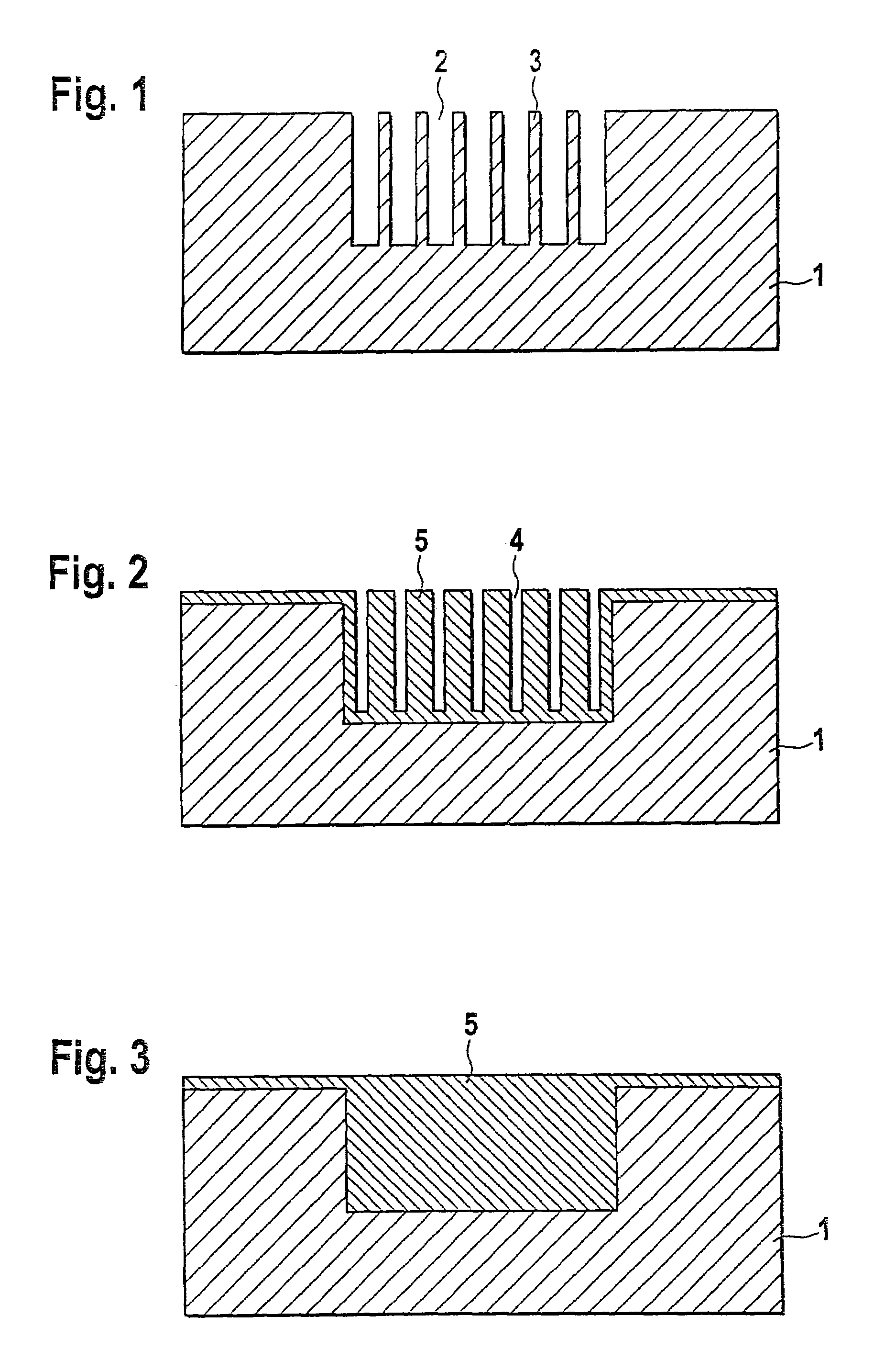
[0040]FIG. 1 shows a silicon substrate 1 in which grooves 2 have already been produced by etching from the upper side. Similar grooves, albeit only up to approx. 20 μm deep and produced for other purposes, may be referred to in other surface micromechanics systems. The width of lands 3 separating grooves 2 is selected so that upon subsequent thermal oxidation, lands 3 are in all cases completely oxidized. The state achieved thereafter is shown for the situation in which the initial width of grooves 2 was selected so that after complete oxidation of lands 3, there remains between them a crevice 4 shown in FIG. 2. The initial width of grooves 2 may also be selected so that grooves 2 are completely closed up (see FIG. 3).

[0041]In order to produce additional cavities, additional grooves may be etched, from the outset, transversely to grooves 2. In this case lands 3 exhibit interruptions and are made up, strictly speaking, of columnar land elements.

[0042]Thermal oxidation is a relatively...


PUM

PropertyMeasurementUnit
thicknessesaaaaaaaaaa
thicknessaaaaaaaaaa
dimensionsaaaaaaaaaa

Abstract

In a mass flow sensor having a layered structure on the upper side of a silicon substrate (1), and having at least one heating element (8) patterned out of a conductive layer in the layered structure, thermal insulation between the heating element (8) and the silicon substrate (1) is achieved by way of a silicon dioxide block (5) which is produced beneath the heating element (8) either in the layered structure on the silicon substrate (1) or in the upper side of the silicon substrate (1). As a result, the sensor can be manufactured by surface micromechanics, i.e. without wafer back-side processes.

Description

FIELD OF THE INVENTION[0001]The invention relates to a micromechanical mass flow sensor using silicon technology. The present invention furthermore relates to a method for manufacturing such a sensor.BACKGROUND OF THE INVENTION[0002]Silicon micromechanics may allow economical mass production of small sensor chips using semiconductor technology methods. Mass flow sensors having dimensions on the order of a few hundred micrometers are used, for example, in the automotive sector to control air delivery.[0003]Mass flow sensors using silicon micromechanics from other systems, for example as discussed in German Published Patent Application No. 195 27 861, encompass a heating element and typically several temperature measurement elements, all of which are patterned out of a metal resistor layer and are positioned on a thin membrane made of dielectric material. The membrane spans a recess in a silicon substrate.[0004]When a flow of medium, in particular an air flow, flows along the upper si...

Claims


Application Information

Patent Timeline
Patent Type & Authority Patents(United States)
IPC IPC(8): C23F1/00G01F1/684G01P5/12G01F1/692H01L37/00
CPCG01F1/6845
Inventor FUERTSCH, MATTHIASFISCHER, FRANKMETZGER, LARSSUNDERMEIER, FRIEDER
Owner ROBERT BOSCH GMBH
Why Eureka
Try Eureka