Metal detector

a metal detector and detector technology, applied in the field of metal detectors, can solve the problems of residual voltage amplitude, non-zero amplitude generation, electrically conductive and ferromagnetic objects affecting the flux linking the receiver coil, etc., and achieve the effect of reducing the problem of contaminant detection

Inactive Publication Date: 2006-06-13
THERMO ELECTRON A DE
View PDF14 Cites 46 Cited by
  • Summary
  • Abstract
  • Description
  • Claims
  • Application Information

AI Technical Summary

Benefits of technology

[0012]It is therefore an object of the present invention to address these problems with the prior art and in particular to provide an improved technique for reducing the contaminant detection problems arising from the bulk effect signal.

Problems solved by technology

Any ferromagnetic or electrically conductive material adjacent to this arrangement causes an imbalance in the flux linking one or other of the receiver coils, so that a voltage of non-zero amplitude is generated in them.
One problem with this arrangement, however, is that both electrically conductive and ferromagnetic objects affect the flux linking the receiver coils.
Unfortunately, many foodstuffs to be monitored are electrically conductive.
Even with this procedure, however, a residual voltage amplitude arises as a product passes through the detector whether or not it contains contaminants.
Such a solution is only partly effective, however, as the bulk effect signal is dependent to a significant degree on the size and shape of the product itself: broadly speaking, larger products generate a bigger bulk effect signal.

Method used


Image

  • Metal detector
  • Metal detector
  • Metal detector

Examples


Embodiment Construction

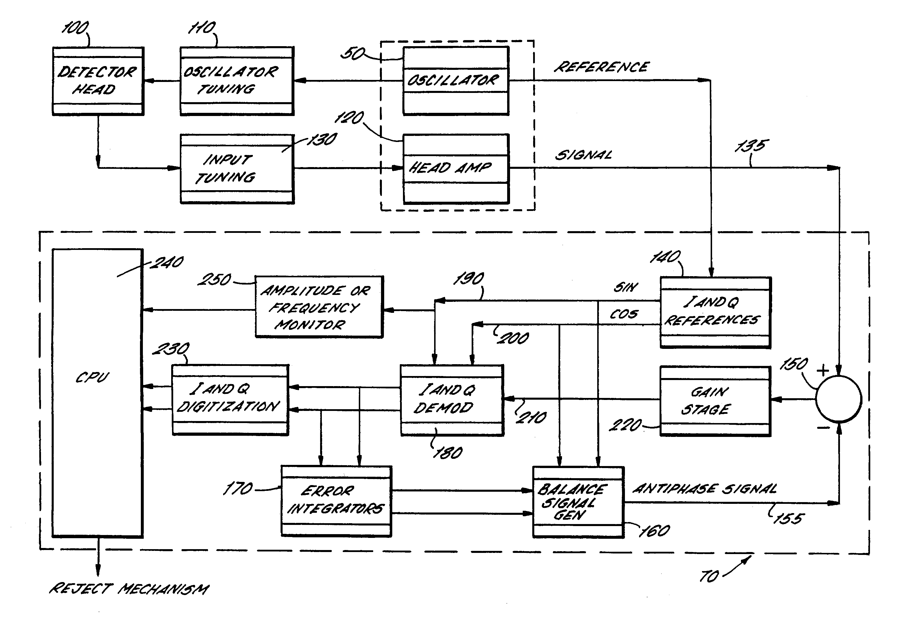
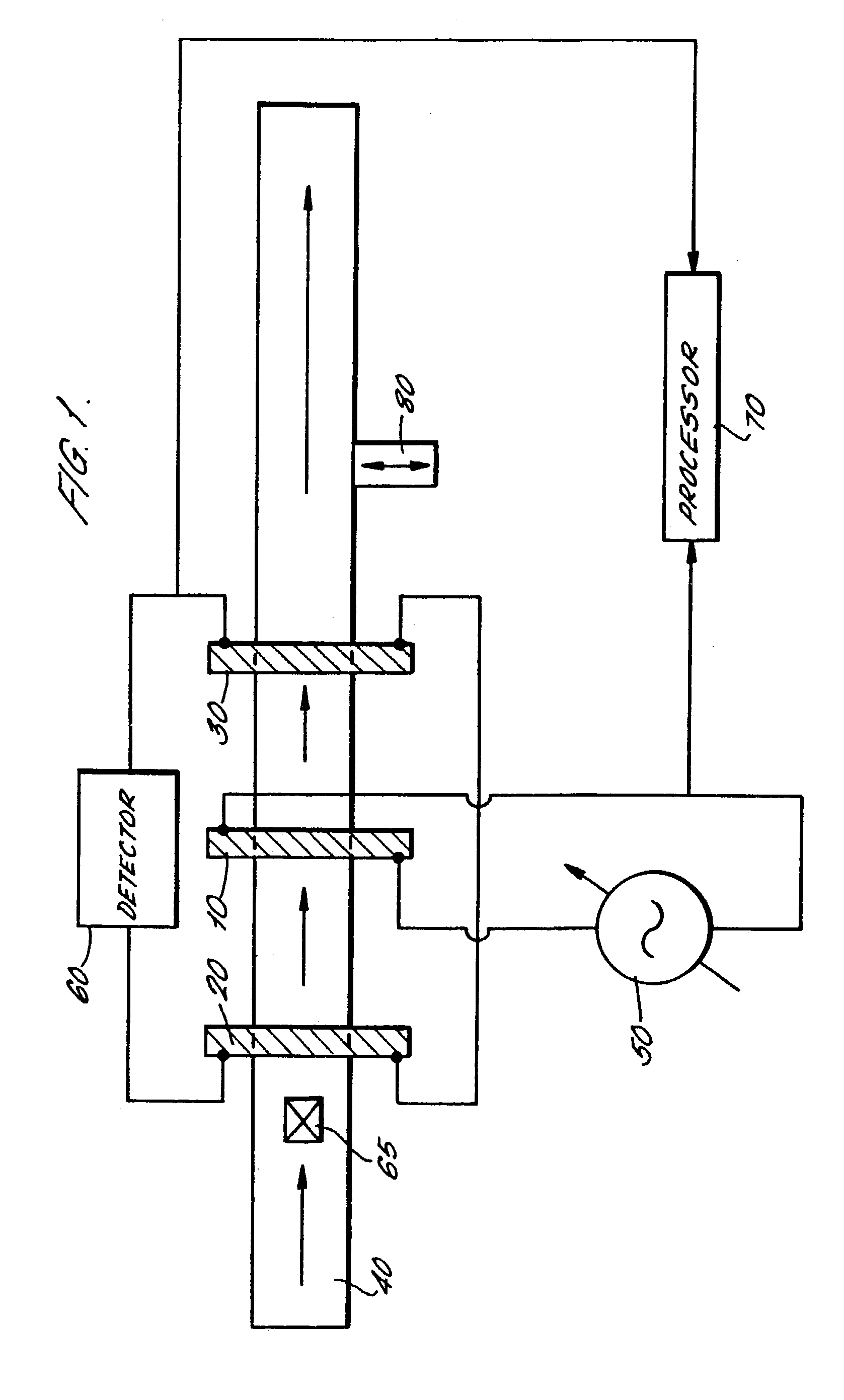
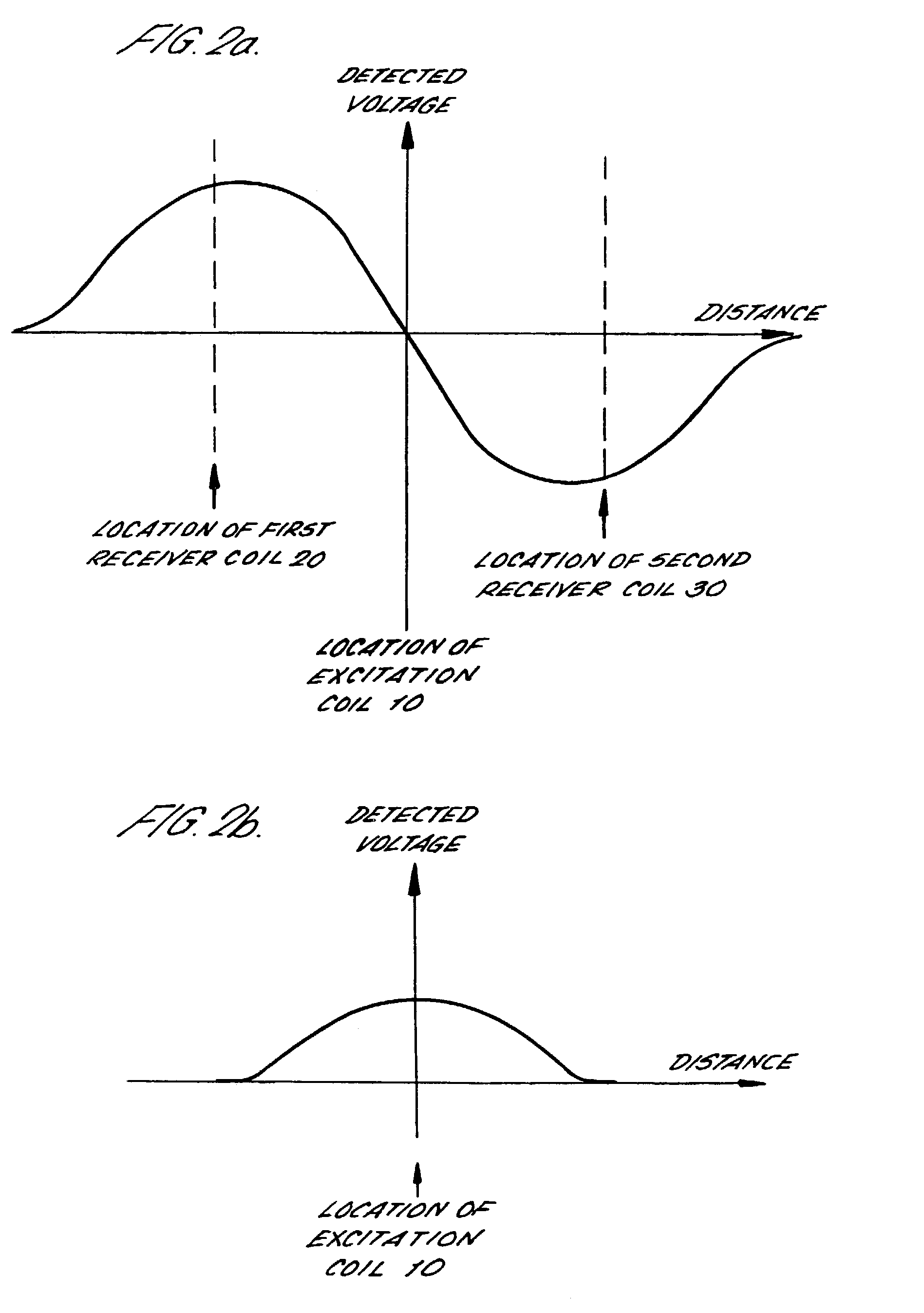
[0029]FIG. 1 shows a highly schematic plan view of a metal detector embodying the present invention. The metal detector comprises a central excitation coil 10 formed as a loop and arranged between two receiver coils 20, 30. The two receiver coils are also formed as loops. Each of the three coils is typically of similar diameter and the three coils are arranged coaxially with one another. The three coils together will be collectively referred to hereafter as the detector head.

[0030]The excitation coil 10 and the two receiver coils 20, 30 of the detector head surround a conveyor 40 which passes generally along an axis perpendicular with the plane of the loops. In FIG. 1, the conveyor is shown moving left to right so that a first receiver coil 20 is upstream of the excitation coil 10, and a second receiver coil 30 is downstream thereof. It will of course be understood that this arrangement is illustrative of the principles only.

[0031]A highly stable, pure sinewave oscillator 50 having ...


PUM

PropertyMeasurementUnit
frequencyaaaaaaaaaa
frequencyaaaaaaaaaa
diameteraaaaaaaaaa

Abstract

A metal detector has a circular excitation coil (10) through which foodstuffs to be tested (65) pass, on a conveyor belt (40). The excitation coil (10) is excited by a stable oscillator (50) and the lines of flux generated by the excitation coil (10) link two receiver coils (20, 30) equidistantly spaced either side of the excitation coil (10). As a foodstuff (65) having a foreign ferromagnetic or electrically conductive object therein passes through the receiver coils (20, 30), a voltage is induced in them. This induced voltage is phase compensated. The change in amplitude or frequency of the oscillator (50) as the foodstuff (65) moves through the excitation coil (10) is also passed to the processor (70) which removes the artifacts from the detector signal caused by the volume of the foodstuff (65) itself. The resultant signal, which was previously swamped by the effect of the volume of the foodstuff itself, can then be detected and the foodstuff can be removed from the conveyor (40).

Description

CROSS REFERENCE TO RELATED APPLICATIONS[0001]The present application claims priority to Great Britain patent application Serial No. 0009936.6, filed Apr. 20, 2000, which applications is incorporated herein in its entirety by this reference.BACKGROUND OF THE INVENTION[0002]This invention relates to a metal detector in particular for the detection of ferromagnetic or electrically conductive foreign matter in foodstuffs and the like.[0003]Metal detectors have been used for many years to screen foodstuffs for the presence of foreign ferromagnetic or electrically conductive objects (usually metallic) which have been introduced during processing or packaging of the food.[0004]One such arrangement is known as an inductive balance metal detector. Here, a central excitation coil is arranged coaxially with a pair of receiver coils. The three coils are typically coaxial and of similar diameter. The receiver coils are spaced equidistantly on either side of the excitation coil, typically with a ...

Claims


Application Information

Patent Timeline
Patent Type & Authority Patents(United States)
IPC IPC(8): G01N27/72G01R33/12G01V3/10
CPCG01V3/105
Inventor BRITTON, ANDREW MICHAEL
Owner THERMO ELECTRON A DE
Why Eureka
Try Eureka