Detection of data transmission rates using passing frequency-selective filtering

Inactive Publication Date: 2006-06-13
IBM CORP
View PDF4 Cites 25 Cited by
  • Summary
  • Abstract
  • Description
  • Claims
  • Application Information

AI Technical Summary

Benefits of technology

[0022]FIG. 6 is a simplified block diagram of a sig

Problems solved by technology

One of the main transceiver module parameters that is an obstacle to multiple bit rate operation is the bandwidth of the receiver path in an optical transceiver.
Transmission errors arise when the optical signal from a lower speed module is presented to a high-bandwidt

Method used


Image

  • Detection of data transmission rates using passing frequency-selective filtering
  • Detection of data transmission rates using passing frequency-selective filtering
  • Detection of data transmission rates using passing frequency-selective filtering

Examples


Embodiment Construction

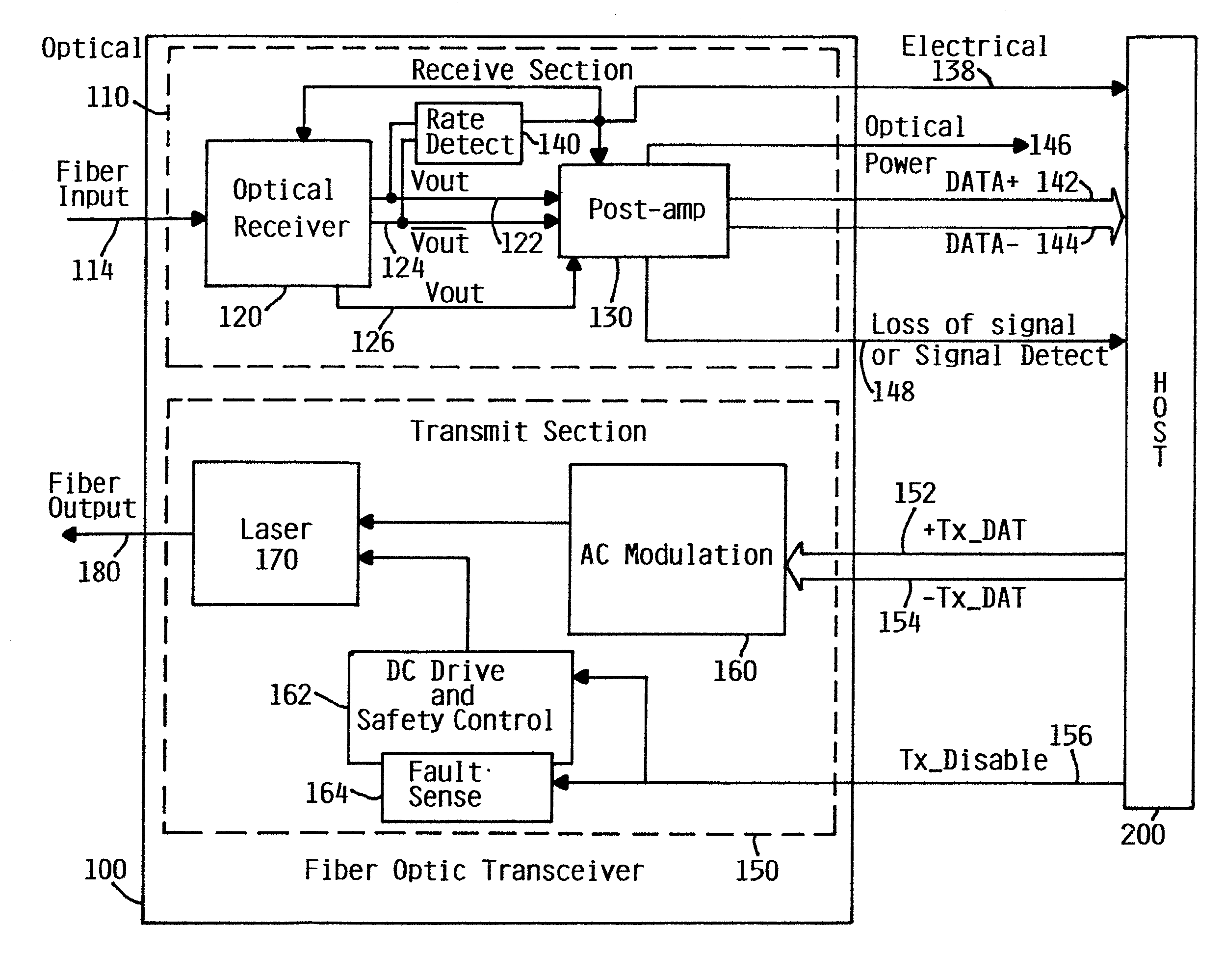
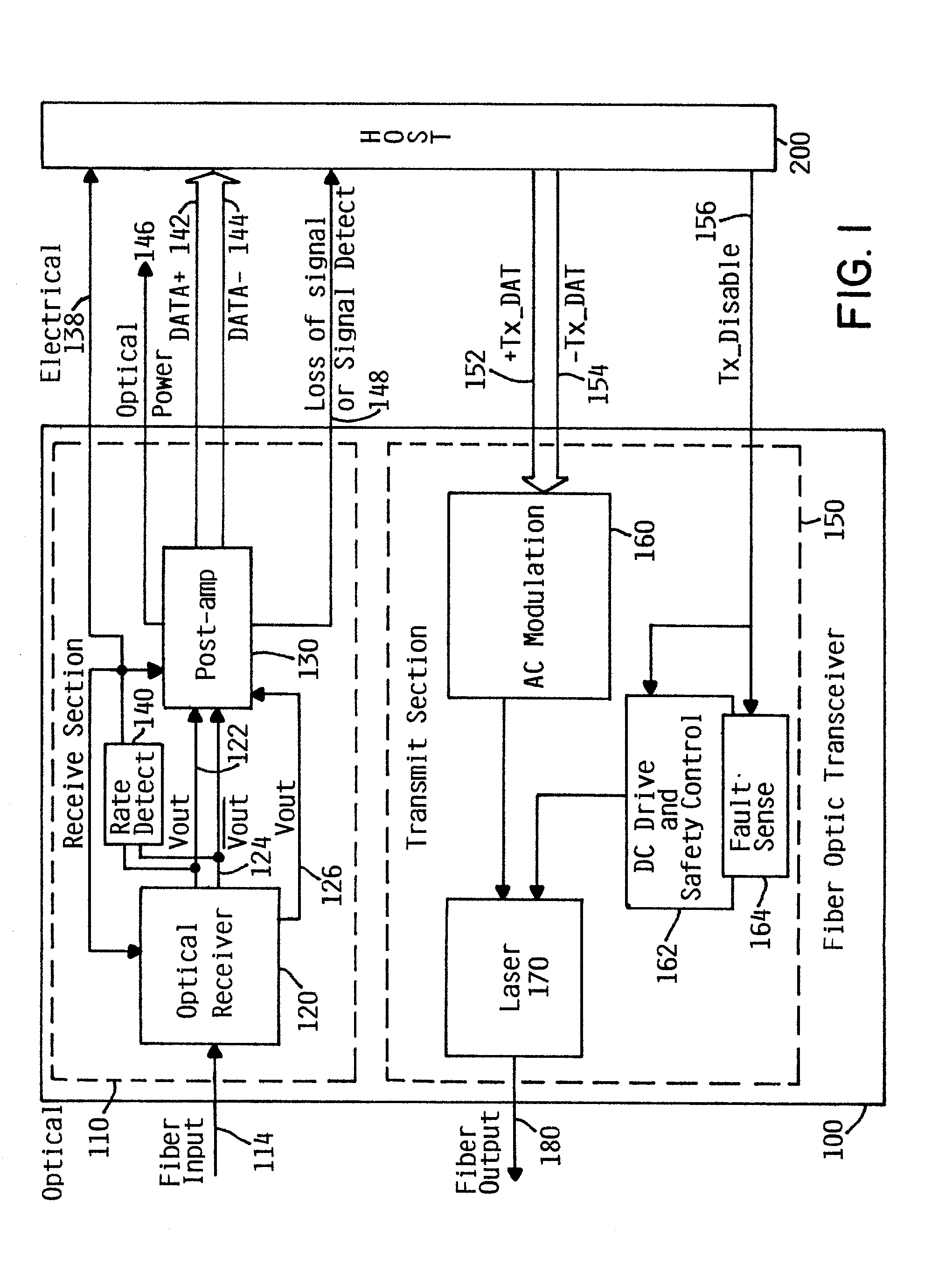
[0023]FIG. 1 is a simplified block diagram of a fiber optic transceiver 100 depicting a receive section 110 and a transmit section 150. The fiber optic transceiver 100 preferably provides a high-speed serial or parallel electrical interface for connecting to a host 200, such as computer or device processors, switches, and peripherals through an optical fiber cable. Specific systems which would benefit from the invention are fiber optic applications in Gigabit Ethernet, Infiniband, OIF, SONET, and Fibre Channel for multi-gigabit data rates. Furthermore, although the integrated circuits herein usually of silicon CMOS and / or bipolar semiconductor technologies, one of skill in the art will understand that other semiconductor materials may be used for other speeds of data transmission or other wavelengths of light. In the Gigabit Ethernet environment, for example, transceiver 100 can be used in such as a host 200 as local area network (LAN) switches or hubs, as well as in interconnecting...


PUM


Abstract

A data receiver, which could be an optical transceiver, a modem, a router hub, is capable of detecting the transmission rate of incoming data. The data is converted to electrical waves appropriate for passive or active bandpass filtering. The frequencies at which the waves are filtered are determined from a plurality of known possible transmission rates and are chosen as having the most detectable difference in the power spectra. By implementing a filter at the corresponding frequency(ies), data having that (those) frequency(ies) will be transmitted. A signal detector then can receive a signal transmitted through the filter and determine the corresponding data rate. It is further contemplated that the multiple frequencies can be filtered by using stages of filters and signal detectors for different frequencies or by filters and detectors capable of multiple frequency operation.

Description

FIELD OF THE INVENTION[0001]This invention relates generally to the field of data transmission and more specifically relates to automatically resolving the rate of data transmission from known data rates by using at least a passing frequency-selective filter and a signal detector.BACKGROUND OF THE INVENTION[0002]Increasingly so, today's communications uses optical data transmitted through, for instance, a fiber optic cable. At the receiving end of a fiber optic link, a photodetector receives the light which may be short wavelength and / or long wavelength light and generates an electrical current proportional to the intensity or power of the light. This photocurrent is then conditioned and coupled to a transimpedance amplifier which converts the photocurrent into a proportionally scaled output voltage signal. The photoreceiver, may be comprised of the photodetector and the transimpedance amplifier, can be packaged into a TO can. On the other end of the TO can are electrical contact pi...

Claims


Application Information

Patent Timeline
IPC IPC(8): H04B10/08H04B17/00H04B3/46H04B10/06H04Q1/20H04B10/00H04B10/04H04B10/14H04B10/158H04B10/26H04B10/43H04L29/08
CPCH04B10/6932
Inventor AMES, STEPHEN JOHNBALL, ROY KEARNSSCHOW, CLINT LEEWHITE, CHRISTOPHER KEITH
Owner IBM CORP
Why Eureka
Try Eureka