
Bus management based on bus status

a multi-functional device and bus management technology, applied in the direction of liquid/fluent solid measurement, process and machine control, instruments, etc., can solve the problems of inflexible bus arrangement, too much needless processing, and bottleneck in bus transfer ability, so as to improve bus efficiency, suppress power consumption, and improve the efficiency of cache use

Inactive Publication Date: 2006-06-13
CANON KK
View PDF56 Cites 14 Cited by
  • Summary
  • Abstract
  • Description
  • Claims
  • Application Information

AI Technical Summary

Benefits of technology

[0012]Accordingly, in view of the first problem set forth above, a first object of the present invention is to provide a bus manager and a control apparatus for a multifunction device having the bus manager in which overall processing speed is raised without requiring the intervention of software for each and every processing operation.
[0013]In view of the second problem set forth above, a second object of the invention is to provide a bus manager and a control apparatus for a multifunction device having the bus manager in which the bus arrangement is provided with flexibility and data transfer can be carried out upon selecting the optimum bus.
[0015]In view of the fourth problem set forth above, a fourth object of the present invention is to provide a bus manager and a control apparatus for a multifunction device having the bus manager in which the efficiency with which a cache is used is improved.
[0016]In view of the fifth problem set forth above, a fifth object of the present invention is to provide a bus manager and a control apparatus for a multifunction device having the bus manager in which the bus used by each bus master is decided dynamically to improve bus efficiency.
[0017]In view of the sixth problem set forth above, a sixth object of the present invention is to provide a bus manager and a control apparatus for a multifunction device having the bus manager in which the operating status of circuitry is monitored to suppress power consumption and, hence, the evolution of too much heat.

Problems solved by technology

A first problem, therefore, is too much needless processing.
Further, owing to handling of a large quantity of data, a bottleneck develops in terms of bus transfer ability owing to use of a single bus.
However, even if a system has a plurality of buses, the bus arrangement lacks flexibility and sufficient transfer capability is not obtained in a case where a large quantity of data is transferred.
This is a second problem with the prior art.
However, in a system configuration in which bus arbitration of these buses and the connection of any one of these buses to the memory are carried out independently, there is a possibility that a plurality of bus masters connected to a plurality of buses will write to the same data space simultaneously, and there is a possibility that the write sequence will not be the sequence in which bus use privilege is obtained by bus arbitration.
This is a third problem of the prior art.
If another device accesses the memory, there is a good possibility of a cache miss.
Though increasing cache storage capacity may appear to be a solution, this leads to a major increase in manufacturing cost.
In particular, when printing or the like is carried out, a large quantity of data that has been read out is delivered to the printer engine and, even though the data has been cached, it is not used twice.
Thus, a fourth problem is that cache memory cannot be used efficiently.

Method used


Image

  • Bus management based on bus status
  • Bus management based on bus status
  • Bus management based on bus status

Examples


Embodiment Construction

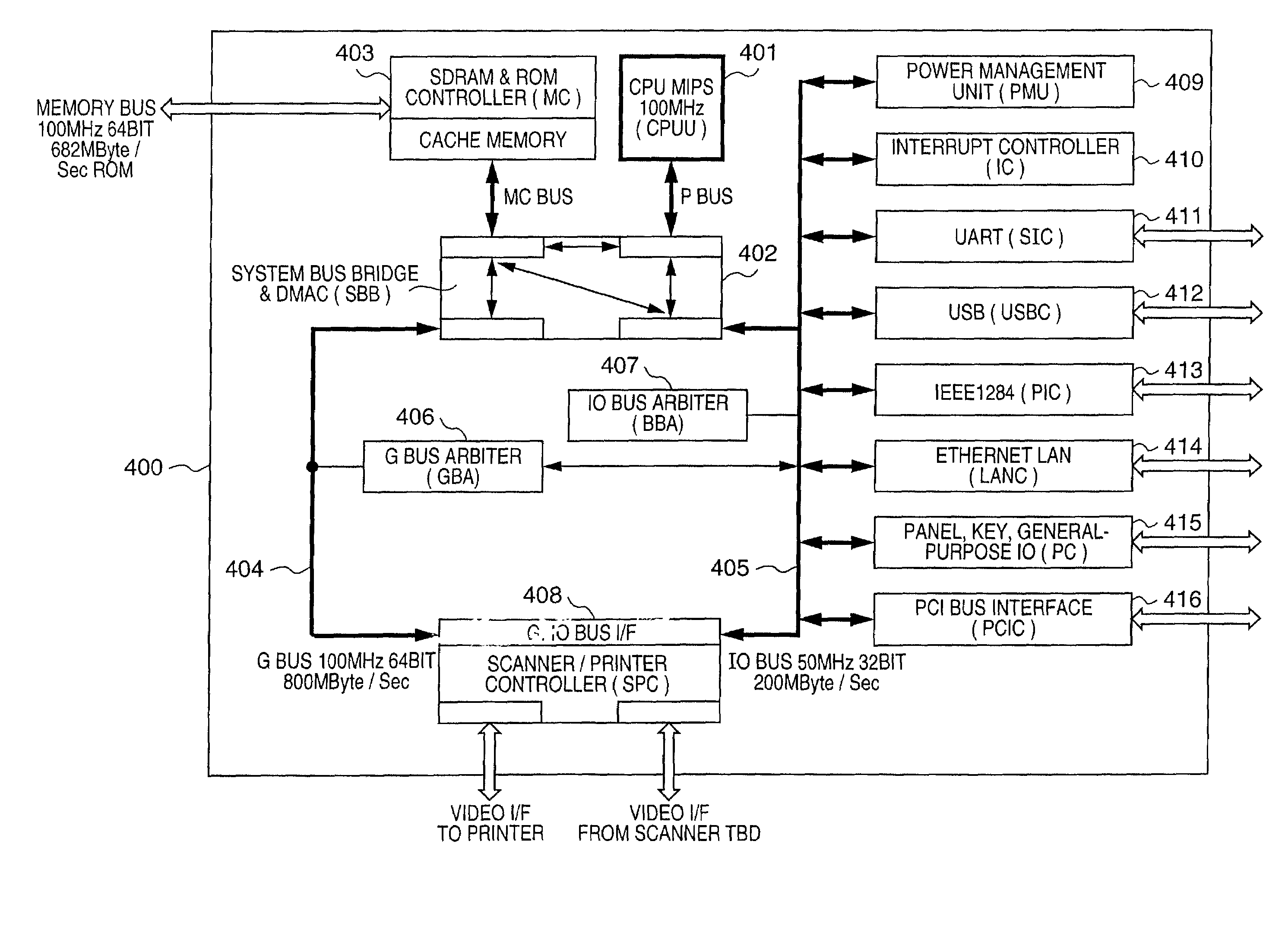
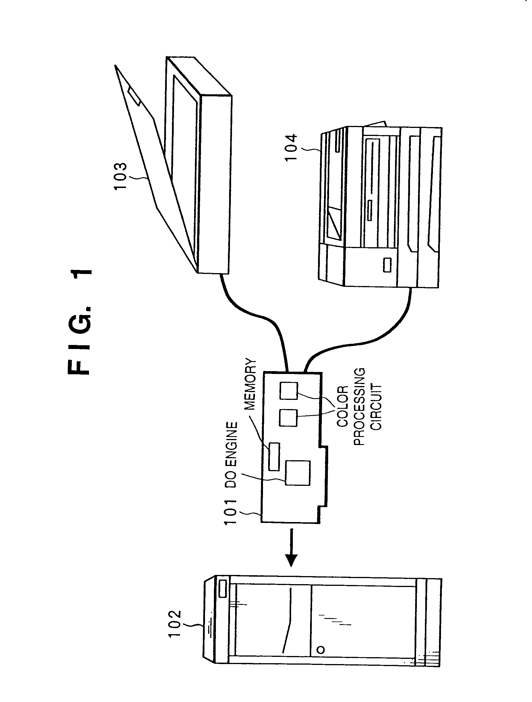
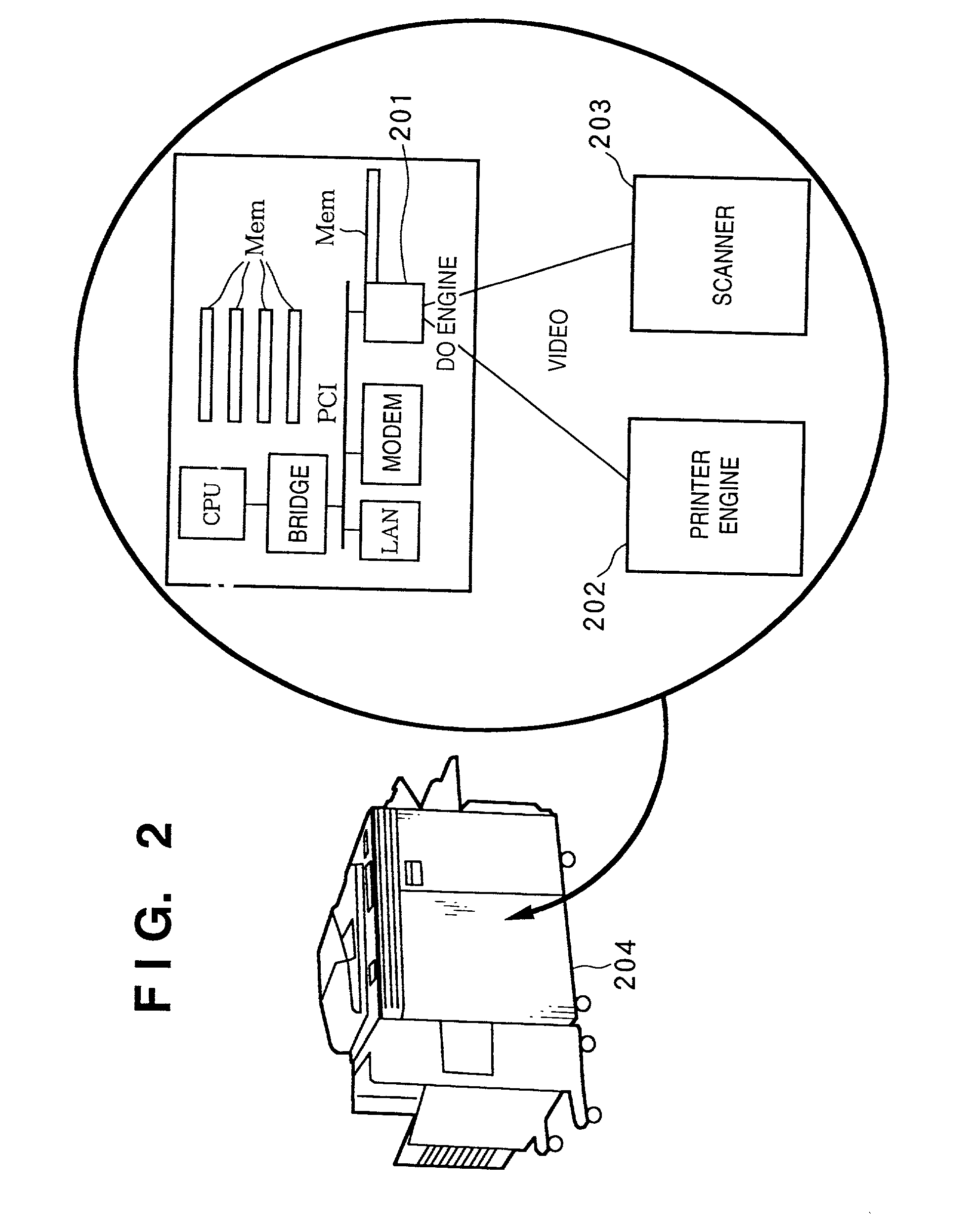
[0092]A so-called “DoEngine” will be described as an embodiment of the present invention. The DoEngine is a single-chip scanning and printing engine having an internal processor core, a processor peripherals controller, a memory controller, a scanner / printer controller and a PCI interface.

[0093]1. Overview of DoEngine

[0094]A DoEngine is a single-chip scanning and printing engine internally incorporating a processor core compatible with the R4000 processor manufactured by MIPS Technologies, Inc., a processor peripherals controller, a memory controller, a scanner / printer controller and a PCI interface. The DoEngine employs high-speed parallel operation and building-block techniques.

[0095]It is possible to internally incorporate a 32-KB cache memory having a maximum of 16 KB of memory for each of transactions and data, an FPU (floating-point operation unit), an MMU (memory management unit) and a user definable coprocessor in the processor shell (the generic term for the processor perip...


PUM


Abstract

A P bus from a CPU, an MC bus from a system memory, an IO bus to which an input / output device has been connected, and a G bus for transferring image data of a scanner / printer controller are connected to a system bus bridge (SBB). The SBB connects any of the P bus, G bus and IO bus as a master and any of the MC bus and IO bus as a slave in dependence upon a request from a master. At this time the P bus and IO bus can be connected in parallel with the G bus and MC bus. As a result, access to the memory by the scanner / printer controller can be carried out in parallel with use of the input / output device by the CPU. This makes it possible to process a large quantity of data, such as image data, efficiently.

Description

CROSS REFERENCE TO RELATED APPLICATION[0001]This application is a division of application Ser. No. 09 / 122,012 filed Jul. 24, 1998 now U.S. Pat. No. 6,438,635, now allowed.BACKGROUND OF THE INVENTION[0002]This invention relates to a control apparatus for a multifunction device for efficient control of an image input unit such as a scanner and an image output unit such as a printer.[0003]Copiers and facsimile machines which combine an image input unit such as a scanner and an image output unit such as a printer, as well as computer systems equipped with these as separate units, are now in practical use. Such systems require the efficient processing of enormous amounts of data in order to handle image data.[0004]Such systems rely upon DMA transfer using a plurality of bus masters in order to transfer data. In a case where a plurality of bus masters execute processing in successive fashion, a series of processing operations is conceivable in which data in memory is first subjected to pr...

Claims


Application Information

Patent Timeline
IPC IPC(8): G06F1/26G05D3/12G06F13/16G06F13/36G06F13/362G06F13/364
CPCG06F13/364
Inventor DATE, ATSUSHIKATO, KATSUNORIYOKOYAMA, NOBORUMAEDA, TADAAKIFUJIWARA, TAKAFUMI
Owner CANON KK
Learn More