
Blow out preventer testing apparatus

Inactive Publication Date: 2006-06-20
COOPER CAMERON CORP
View PDF42 Cites 53 Cited by
  • Summary
  • Abstract
  • Description
  • Claims
  • Application Information

AI Technical Summary

Benefits of technology

[0036]This invention is a system and technique which can accurately quantify tests and improve testing practices, jointly raising the level of safety and the commercial aspect of the well operation.

Problems solved by technology

A blow out can result in a major leak to the environment which can ignite or explode, jeopardizing personnel and equipment in the vicinity, and pollution.
Failure to do so caused by weather conditions, current forces, equipment malfunctions, drift off or drive off, fire or explosion, collision or other marine incidents means it is necessary if possible to make the well safe, isolate the well at the seabed and disconnect the riser system.
A faulty diagnosis or incorrect interpretation due to vague information could lead to the well being temporarily suspended and the BOP assembly being pulled.
If a leak occurred from the BOP bore test past the wellhead test tool, the well could be pressured up and be hydraulically fractured, thus making the well unusable.
Either way, after the mechanical release or if a solid wellhead test tool is run, the integrity of the wellhead test tool to seal off in the wellhead cannot be verified before tested.
Even though the shear blind ram BOP cavity is a critical zone to test, the consequences of jeopardizing the integrity of the well casing is deemed too high a risk.
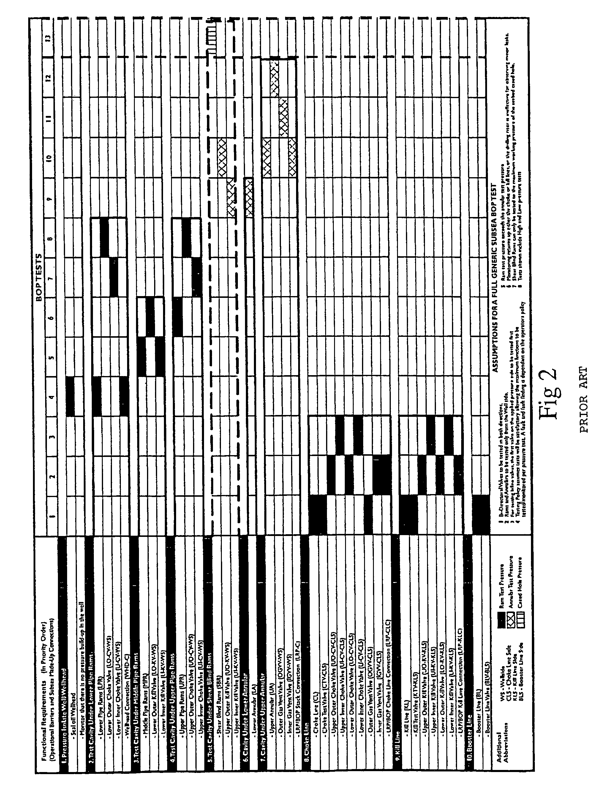
In addition, this conventional test procedure using the choke and kill lines involves a high volume relative to the small tested cavity volume above the wellhead test tool and in relation to any leaks, meaning that it is difficult to detect leaks.
This is a time consuming process which greatly lengthens the testing time.
The compressibility of the drilling liquids, usually drilling mud, and possible expansion or elongation of the lines to the BOP and variations in temperature all contribute to the difficulty of monitoring very small changes in the volume.
However, when testing, there is a degree of interpretation required as to whether the decays are caused by the above mentioned side effects or a leak.
A stationary column of well liquid could unknowingly allow migration of formation fluid into the well bore and the properties of the well liquid could change due to deterioration, thus creating an unstable situation which could result in a kick.
Therefore, allowing an open hole to stand stationary for any period of time is an unwise practice.
This cannot be achieved if there is a one-way upward flow mechanism in the wellhead test tool or a solid wellhead test plug has been used which would prevent circulation, endangering the operation.
However, this has inherent problems due to possible leakage between the seals of the telescopic portions which makes it very difficult to distinguish a failed BOP.
Circulation of the well after testing is not possible unless wireline is run down the drill pipe to remove the blanking dart.

Method used


Image

  • Blow out preventer testing apparatus
  • Blow out preventer testing apparatus
  • Blow out preventer testing apparatus

Examples


Embodiment Construction

[0036]This invention is a system and technique which can accurately quantify tests and improve testing practices, jointly raising the level of safety and the commercial aspect of the well operation.

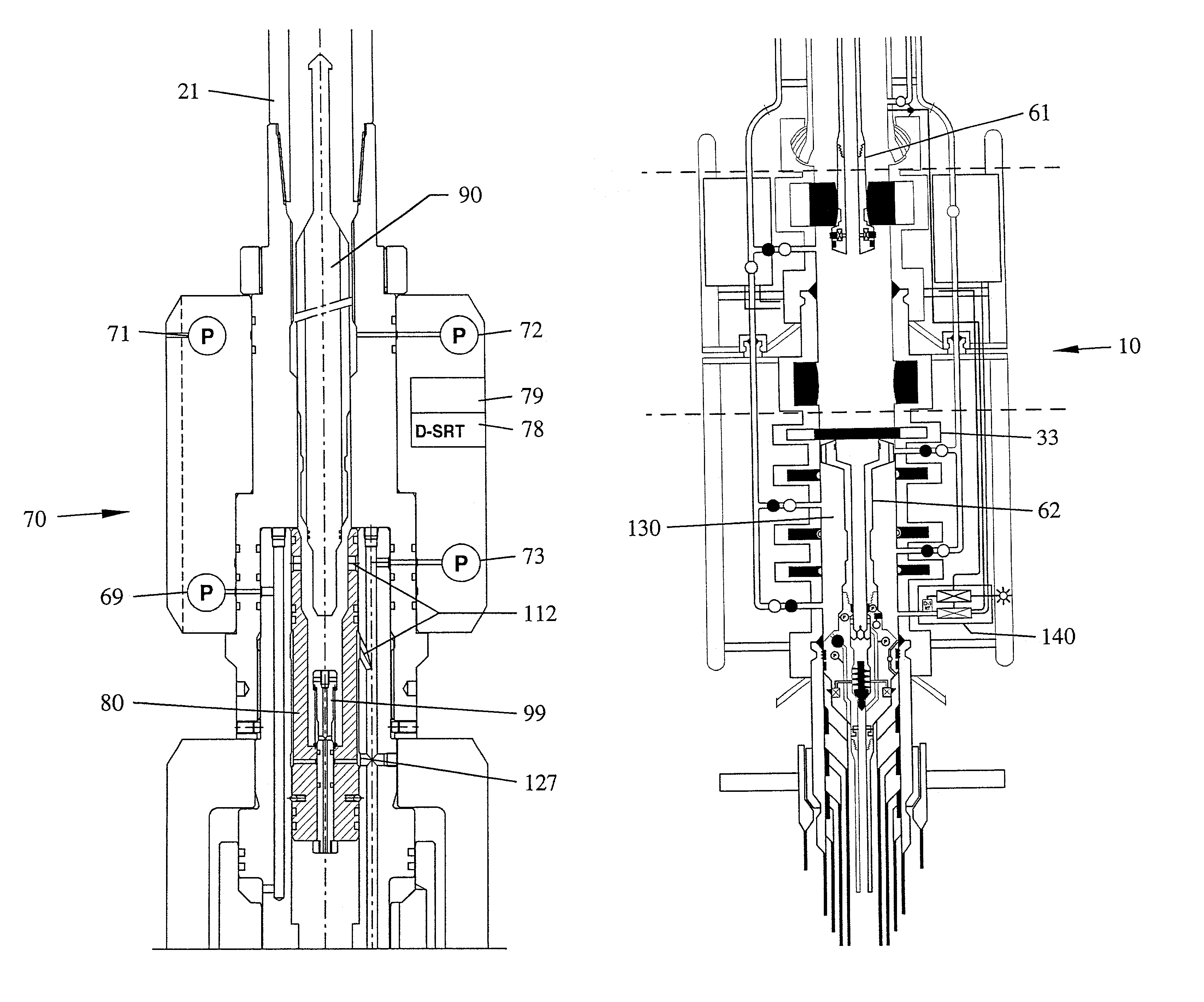
[0037]According to the present invention there is provided an apparatus for registering parameters in the bore of a member which is, in use, connected to a pressurized housing, the apparatus comprising:

[0038]an electro-control package for attachment, in use, to the member;[0039]the test assembly placed, in use, in the member;[0040]the electro-control package and the test assembly having means for sending signals to and receiving signals from one another.

[0041]Preferably, the test assembly is one of the following: blow out preventer test assembly, wellhead tubing hanger running tool, spool tree or horizontal tree tubing hanger running and test tool, casing and seal assembly running tool, subsea test tree, wireline or coil tubing tool, hanger or plugs.

[0042]According to a second aspect of t...


PUM


Abstract

The consequences of any failure of a blow out preventer assembly to operate correctly in an emergency can be far reaching. Thus, there is provided an apparatus for registering parameters in the bore of a member which is, in use, connected to a pressurised housing, the apparatus comprising: an electro-control package for attachment, in use, to the member; a test assembly placed, in use, in the member; the electro-control package and the test assembly having means for sending signals to and receiving signals from one another.

Description

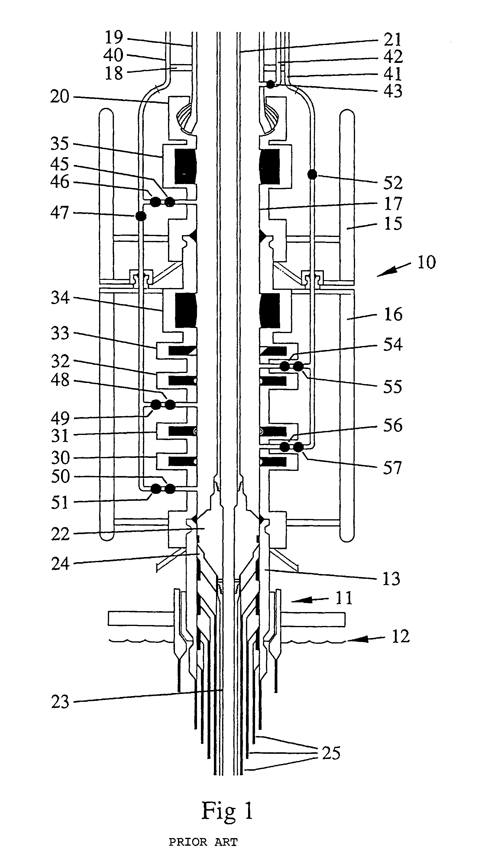
CROSS-REFERENCE TO RELATED APPLICATIONS[0001]This application claims a right of priority based upon European Patent Application No. 01305431.7, as filed in the European Patent Office on Jun. 22, 2001.STATEMENT REGARDING FEDERALLY SPONSORED RESEARCH OR DEVELOPMENT[0002]Not Applicable.BACKGROUND OF THE INVENTION[0003]1. Field of the Invention[0004]This invention relates to a testing apparatus to test a Blow Out Preventer (BOP) stack or assembly and to a method of testing using such an apparatus.[0005]2. Description of the Related Art[0006]A BOP assembly is a multi closure safety device which is connected to the top of a drilled and often partially cased hole. The accessible top end of the casing is terminated using a easing spool or wellhead housing upon which the BOP assembly is connected and sealed.[0007]The wellhead and BOP stack (the section in which rams are provided) must be able to contain fluids at a pressure rating in excess of any formation pressures that are anticipated whe...

Claims


Application Information

Patent Timeline
IPC IPC(8): E21B47/06E21B33/06E21B47/10
CPCE21B33/061E21B47/1025E21B33/063E21B47/117
Inventor COUREN, PATRICE PAUL LOUISHOPPER, HANS PAUL
Owner COOPER CAMERON CORP
Learn More