
Circular heat sink assembly

a heat sink and assembly technology, applied in the direction of fluid heaters, air heaters, lighting and heating apparatus, etc., can solve the problems of low density (total heat dissipating area per unit volume) of heat sinks that combine several heat dissipating fins together, and cannot achieve thin thickness, so as to improve the heat dissipating performance, improve the fan-shaped heat dissipating fins, and improve the effect of heat dissipation performan

Inactive Publication Date: 2006-06-20
HUANG CHU TSAI
View PDF14 Cites 45 Cited by
  • Summary
  • Abstract
  • Description
  • Claims
  • Application Information

AI Technical Summary

Benefits of technology

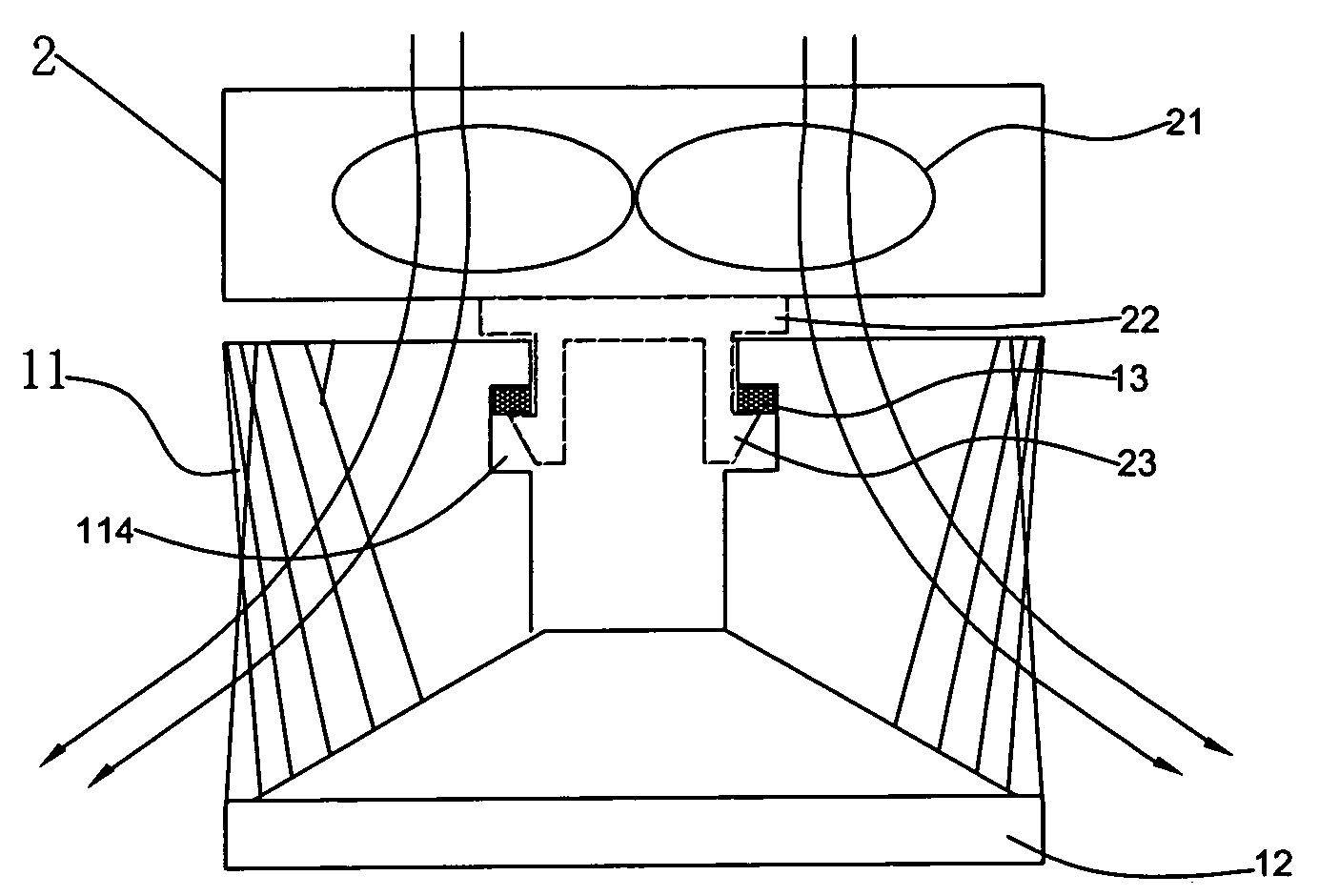
[0008]The primary objective of the present invention is to improve the fan-shaped heat dissipating fins being stacked with each other into a circular heat sink assembly as disclosed in the R.O.C. Utility Model Patent No. 196973 (the term of the patent right is from Oct. 21, 2001 to Jul. 15, 2013 and the inventor of this utility model patent is the same inventor of the present invention). The present invention provides a circular heat sink assembly with a conical base that comprises a plurality of heat dissipating fins with an aslant and curved bottom, and these heat dissipating fins are stacked together into a conical shape and coupled to a conical base to form a heat sink. The heat sinks of this sort have simple structure, an easy way for its manufacture and a better heat dissipating performance than the prior-art heat sinks.

Problems solved by technology

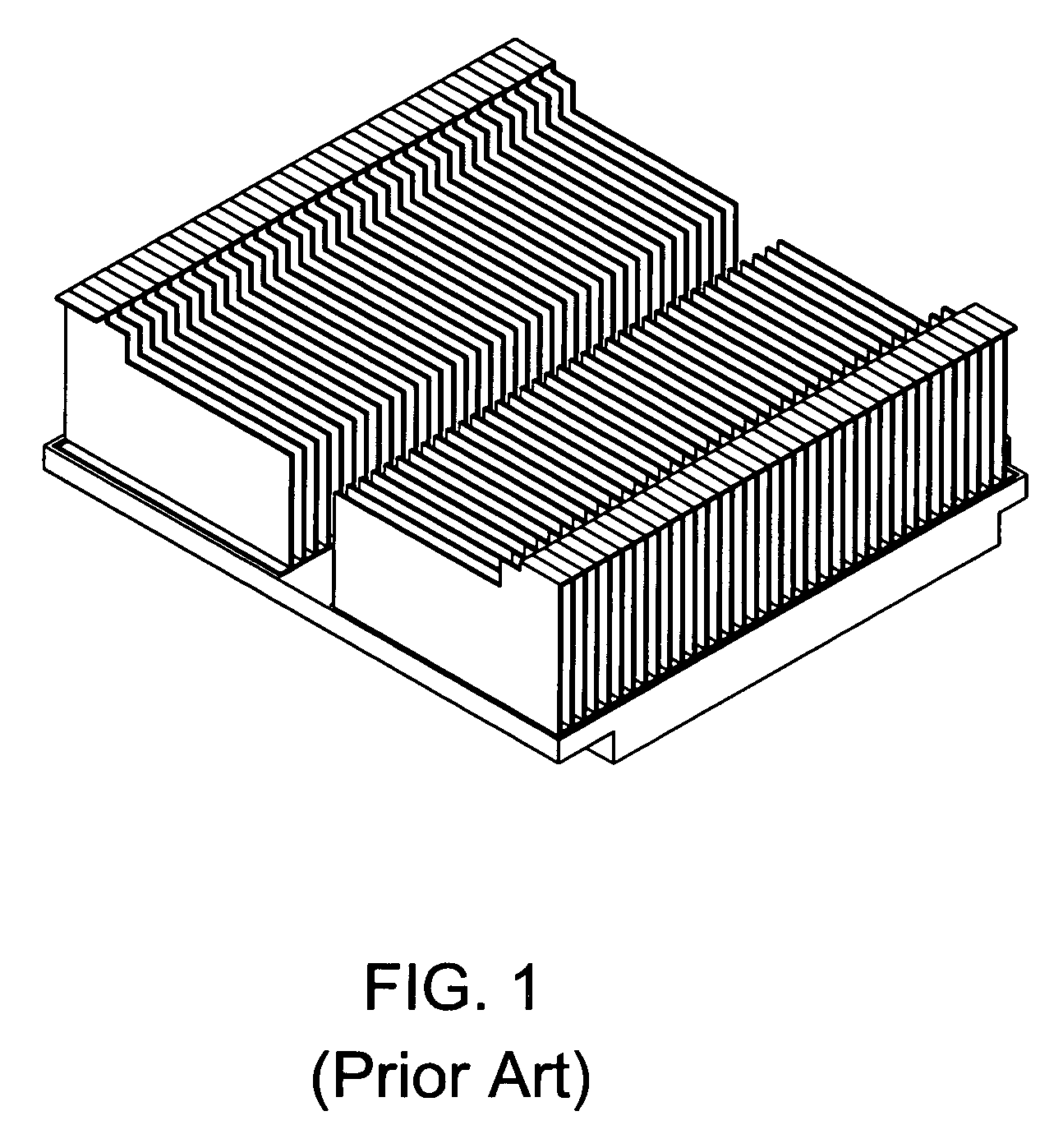
However, all of the foregoing three manufacturing methods can be adopted for manufacturing the parallel heat sinks, but a very thin thickness cannot be achieved during the manufacture of an extruded aluminum or a compressed aluminum heat sink due to the limitations of the mechanical manufacturing capability, and thus the density (total heat dissipating area per unit volume) of a heat sink that combines several heat dissipating fins together is low.
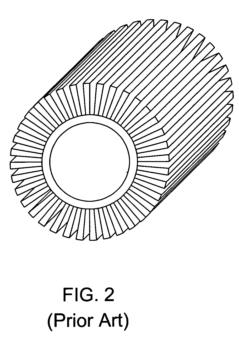
Further, at present, the circular heat sinks only adopt an aluminum extrusion method or an aluminum compression method for manufacturing the heat dissipating fins and seldom use the stacking method for the manufacture at all.

Method used


Image

  • Circular heat sink assembly
  • Circular heat sink assembly
  • Circular heat sink assembly

Examples


Embodiment Construction

[0059]Please refer to FIGS. 4 to 8 for the first preferred embodiment of the present invention. The present invention provides a circular heat sink assembly having a heat dissipating fin with a streamlined curved surface. The circular heat sink assembly comprises a circular heat sink 1 having a plurality of heat dissipating fins 11 with a single streamlined curved surface and being connected to a conical heat dissipating base 12 to form the circular heat sink. Each single heat dissipating fin 11 comprises a main body 111 as shown in FIG. 5, and a side of the main body 111 being coupled to a folded flange 111 on a side and a fan-shaped folded flange 112 at the bottom. Both ends of the fan shape use the same concentric point and different radii to form two arc sections of different lengths and a groove 114 is disposed at the central position of the main body 111 as shown in FIG. 5.

[0060]The plurality of single heat dissipating fins 11 uses a pressing section to tightly align the singl...


PUM


Abstract

The present invention discloses a circular heat sink to improve a traditional extruded aluminum heat sink or a traditional compressed aluminum heat sink by adopting a plurality of streamlined curved heat dissipating fins and a conical base to constitute the circular heat sink. The shape of the heat dissipating fin is designed to have a streamlined curved surface; and the circular heat sink assembly comprises a plurality of fan-shaped heat dissipating fins stacked and encircled into a circular shape and the curvature of the bottom of the heat dissipating fin can be designed according to the conical shape of the conical base, and a latch structure for the heat dissipating fin is adopted. If the plurality of the heat dissipating fins with a streamlined curved surface is stacked into a circular shape, then a plurality of folded flanges along the sides of the plurality of heat dissipating fins are latched and encircled to form a circular ring, and the fan-shaped folded flanges at the bottom of the heat dissipating fins also are stacked and encircled to form a circular ring and then connected to a conical base to form a circular heat sink having a plurality of streamlined heat dissipating fins with a curved surface.

Description

BACKGROUND OF THE INVENTION[0001]1. Field of the Invention[0002]The present invention relates to a circular heat sink assembly, more particularly to a heat sink assembly capable of saving its assembling time and maximizing its heat dissipation effect.[0003]2. Description of the Related Art[0004]As the computer industry is blooming, the product design for computers tends to be light, thin, short, and compact and the quantity of heat produced by electronic components such as a microprocessor and a chip is getting larger and larger, so that heat dissipation becomes an important subject for maintaining a normal operation of computer systems. As to the methods for dissipating heat from a computer system, a plurality of heat dissipating fins is generally used to be attached onto the surface of a heat generating electronic component and works together with a fan to dissipate the heat out of the computer system and prevents an electronic component from being overheated or burned as well as ...

Claims


Application Information

Patent Timeline
Patent Type & Authority Patents(United States)
IPC IPC(8): H05K7/20H01L23/467
CPCH01L23/467F21V29/773H01L2924/0002H01L2924/00
Inventor HUANG, CHU-TSAI
Owner HUANG CHU TSAI
Learn More