Multi-spectral uniform light source

a light source and multi-spectral technology, applied in the manufacture of electric discharge tubes/lamps, instruments, electrode systems, etc., can solve the problem of lack of uniform illumination

Inactive Publication Date: 2006-06-20
WAFERMASTERS
View PDF27 Cites 1 Cited by
  • Summary
  • Abstract
  • Description
  • Claims
  • Application Information

AI Technical Summary

Benefits of technology

[0006]In accordance with this invention, a multi-purpose, multi-spectral light source allows gases inside a light source to be exchanged. An advantage of the present invention is that the light source is not limited to a single gas. The gases within the light source may be exchanged in order to use the same light source for a variety of different applications which require different spectrums of light. Each gas emits a particular spectrum of light which is useful for a number of applications. The instant invention may be used for any number of applications requiring light, including but not limited to wafer surface conditioning, U.V. cleaning, wafer heating, U.V. curing, annealing, drying, enhancing photochemical reaction, photo enhanced processing, sterilization, backlighting, signs, and U.V. light.
[0007]In accordance with one embodiment of this invention, a light source serves a variety of applications by merely exchanging the gas(es) within the light source. In another embodiment of this invention, constant pressure and / or constant current may be maintained within the light source during gas exchange.
[0008]In accordance with one embodiment of this invention, a multi-spectral light source includes a hollow vessel with a first end and a second end; a first valve located at the first end; a second valve located at the second end; an electrode located at each end; and a pump for pumping a gas into and out of the vessel. The vessel includes a hollow tube in a variety of cross-sectional as well as longitudinal shapes. The gases used include, but are not limited to, krypton (Kr), argon (Ar), neon (Ne), xenon (Xe), helium (He), mercury (Hg), neon / helium mixture, neon / argon mixture, oxygen (O2), hydrogen (H2), ditrium (D2), nitrogen (N2) and various mixtures of the preceding gases. All gases can be mixed except for hydrogen and oxygen.
[0009]The gases in the light source may be exchanged in order to use the same light source for a variety of different applications which require different spectrums of light. The gases are exchanged by unsealing the seals of the light source; pumping a first gas initially located within the light source out of the light source; pumping a second gas into the light source; and then sealing each seal of the light source. A variety of valves are used to seal and unseal the light source.
[0010]By changing the type of gas used inside the light source, gas pressure inside the light source, excitation level (i.e., the voltage, current, and / or frequency required to illuminate the light source) or excitation method (i.e., whether the lamp is illuminated by conventional means, microwave or RF), the lamp of this invention will emit different spectra of light. Thus, the characteristics of the light source can be modulated when the light source is in use. The single light source of this invention replaces the use of a number of different light sources. For example, instead of being required to move a workpiece around to several different stations, each station with its own light source for a specific purpose, a single station using the multi-spectral light source of this invention can replace these several different stations.
[0011]This invention will be more fully understood in light of the following detailed description taken together with the accompanying drawings.

Problems solved by technology

However, such light sources tend to be limited to a single application, may lack uniformity of illumination, and are only useful in a limited number of environments.

Method used


Image

  • Multi-spectral uniform light source
  • Multi-spectral uniform light source
  • Multi-spectral uniform light source

Examples


third embodiment

[0035]In accordance with this invention, the invention includes a lamp array 30 of N serially connected, relatively planar straight tubes 31-1 to 31-N (where N is a selected integer), as seen in FIG. 3. The array 30 includes a plurality of individual straight tubes 31-1 to 31-N, each tube having two sealed ends 32. Endcaps 37 are on ends 32 of each of tubes 31-n (where 1≦n≦N). A parallel plate 33 or other filament serves as an electrode and connects endcaps 37 of neighboring tubes 31-n and 31-(n+1) or 31-n and 31-(n−1). Each parallel plate 33 (there are N-1 parallel plates in the structure of FIG. 3) provides a relatively large electrode area to maximize uniform discharge.

[0036]It is preferred to use a parallel plate 33 electrode since a point electrode does not provide as uniform a discharge as an electrode with a larger contact area because the larger the electrode area, the more uniform the discharge. As seen in FIG. 8A, tube 81 includes a point electrode 83 at each of end of tub...

fourth embodiment

[0041]In accordance with this invention, the invention includes a light source 45 comprising a single rectangular planar tube 40, as seen in FIGS. 4A and 4B at constant pressure and constant current. Single rectangular wide area planar tube 40 has two ends 41A, 41B with an electrode 42 placed at each end. Endcap 47 (not shown) is configured to the shape of tube 40 and one endcap 47 is placed on each end 41A, 41B of tube 40. A conductor 43 runs along the width of each end 41A, 41B of tube 40 so as to provide uniform illumination. Uniform illumination along the width of tube 40 results from conductor 43 being in contact with gas along the width of tube 40. Each conductor 43 is in contact with an electrode 42. The distance between electrodes 42 is constant so as to prevent arcing. Pressure inside and outside the envelope 40 is kept in close proximity to prevent the lamp from breaking. As discussed above, a tube with a rectangular cross-section is not as structurally strong as a tube of...

fifth embodiment

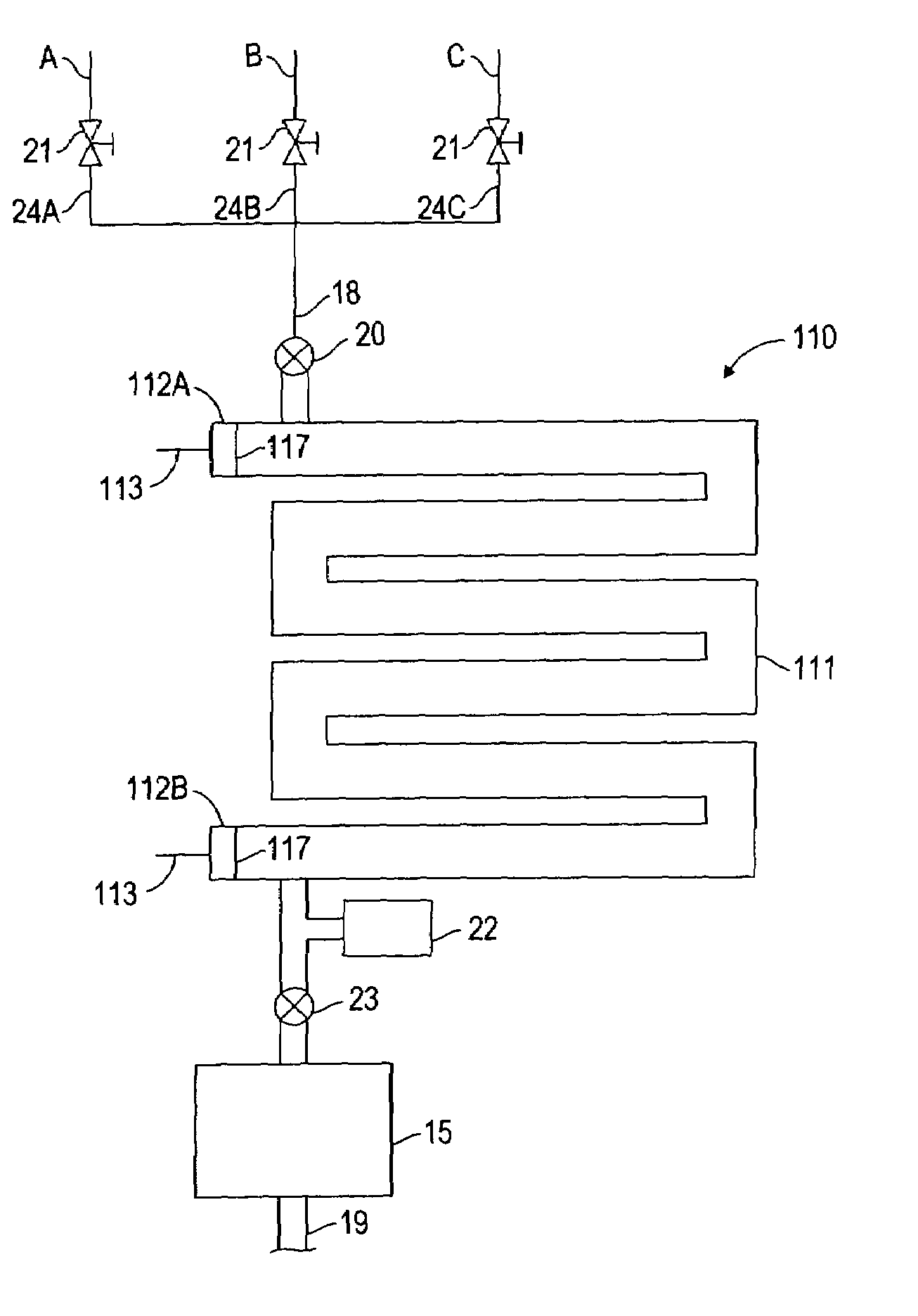
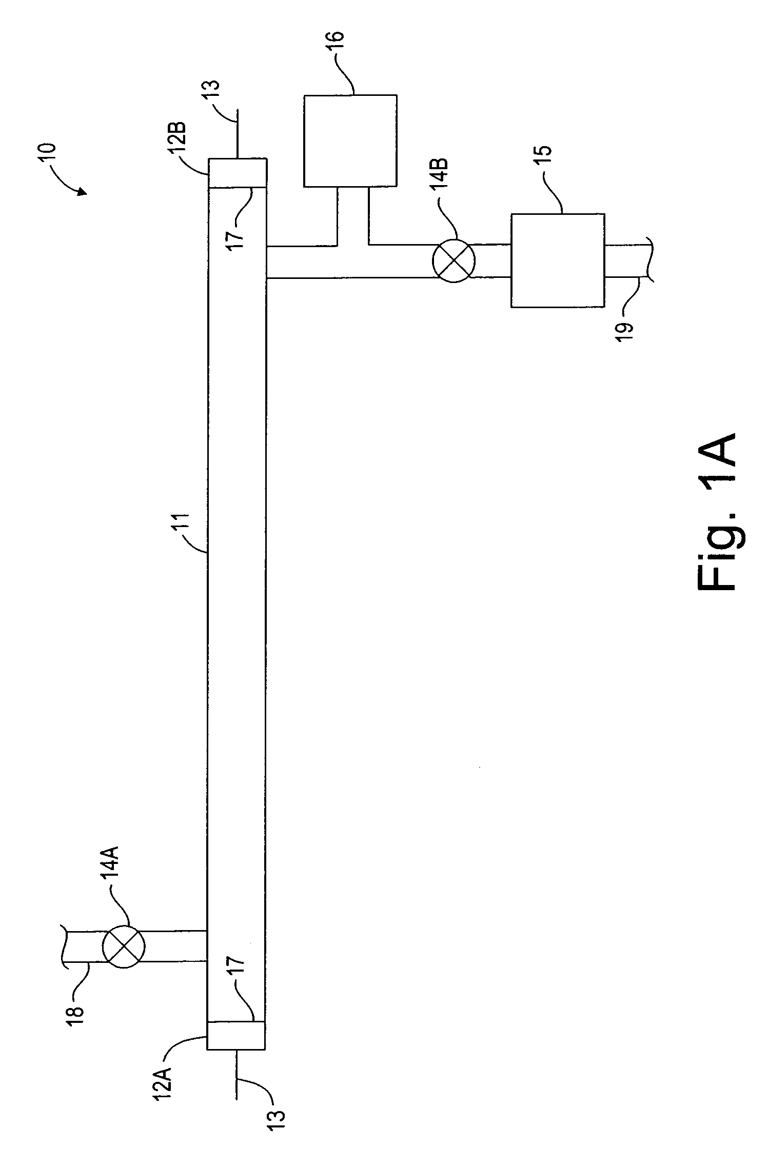
[0042]In accordance with this invention, the invention includes a spiral-shaped tube 51, as seen in FIG. 5, at constant pressure and constant current. Light source 50 includes a single spiral-shaped tube or envelope 51 with two sealed ends 52A, 52B. Each end 52A, 52B of tube 51 has an endcap 57. Each endcap 57 of tube 51 has an electrode 53 for power. An incoming gas line 18 runs from a gas source (not shown) to a valve 14A on incoming end 52A of the tube. Valves 14A, 14B are placed at or near each end 52A, 52B. Valves 14A, 14B may be opened / closed in several ways, including but not limited to, manually and pneumatically. A pump 15 for pumping the gas is operationally connected to valve 14B on outgoing end 52B of tube 51. An outgoing gas line 19 runs out from pump 15. A pressure measuring device 16 is connected to tube 51 so as to measure pressure within tube 51. A factor affecting uniformity of illumination is the uniformity of pressure within tube 51 along the length of tube 51.


PUM

PropertyMeasurementUnit
pressureaaaaaaaaaa
pressureaaaaaaaaaa
pressureaaaaaaaaaa

Abstract

A multi-spectral uniform light source provides a single light source for a variety of applications. The gas or gases inside the light source may be exchanged for another gas or gases depending on the desired application and need for a particular wavelength of emitted light.

Description

BACKGROUND OF THE INVENTION[0001]1. Field of the Invention[0002]This invention relates generally to gas discharge light sources and more particularly to gas exchangeable light sources.[0003]2. Description of Related Art[0004]Light sources are used for any number of applications requiring light, including but not limited to U.V. cleaning, U.V. curing, annealing, drying, photo enhanced processing, sterilization, backlighting, signs and U.V. light. However, such light sources tend to be limited to a single application, may lack uniformity of illumination, and are only useful in a limited number of environments. Therefore, in order to accomplish a variety of different applications, a number of different light sources are required; each intended for a specific purpose. This may require, for example, that a workpiece be moved around to several different stations, each station with its own light source for a specific purpose.[0005]A need exists for a lamp that does not need to be replaced ...

Claims


Application Information

Patent Timeline
Patent Type & Authority Patents(United States)
IPC IPC(8): H01J9/395G03F7/20H01J61/00H01J61/12H01J61/16H01J61/28H01J61/32H01J61/38
CPCG03F7/70016H01J9/395H01J61/00H01J61/12H01J61/16H01J61/38H01J61/32H01J61/28H01J61/305H01J61/307H01J61/322H01J61/327
Inventor YOO, WOO SIK
Owner WAFERMASTERS
Why Eureka
Try Eureka