Multiple beam steered subarrays antenna system

a technology of antenna system and subarray, applied in the field of antenna systems, can solve the problems of large number of amplifiers, and high cost and power requirements of the antenna system, and achieve the effect of improving reliability

Inactive Publication Date: 2006-06-20
THE AEROSPACE CORPORATION
View PDF10 Cites 30 Cited by
  • Summary
  • Abstract
  • Description
  • Claims
  • Application Information

AI Technical Summary

Benefits of technology

[0006]An object of the invention is to provide a pha

Problems solved by technology

However, conventional discrete FET phase shifters used for antenna beam steering are costly and have undesirable high insertion loss, especially at high frequencies.
Very large arrays require a large number of amplifiers to compensate for this high insertion loss.
A large number of amplifier leads to high cost and power requirements for the antenna system.
The use of MEMS phase shifters can lead to mass and cost reductions, but due to limitations on the number of MEMS phase shifter changes over o

Method used


Image

  • Multiple beam steered subarrays antenna system
  • Multiple beam steered subarrays antenna system
  • Multiple beam steered subarrays antenna system

Examples


Embodiment Construction

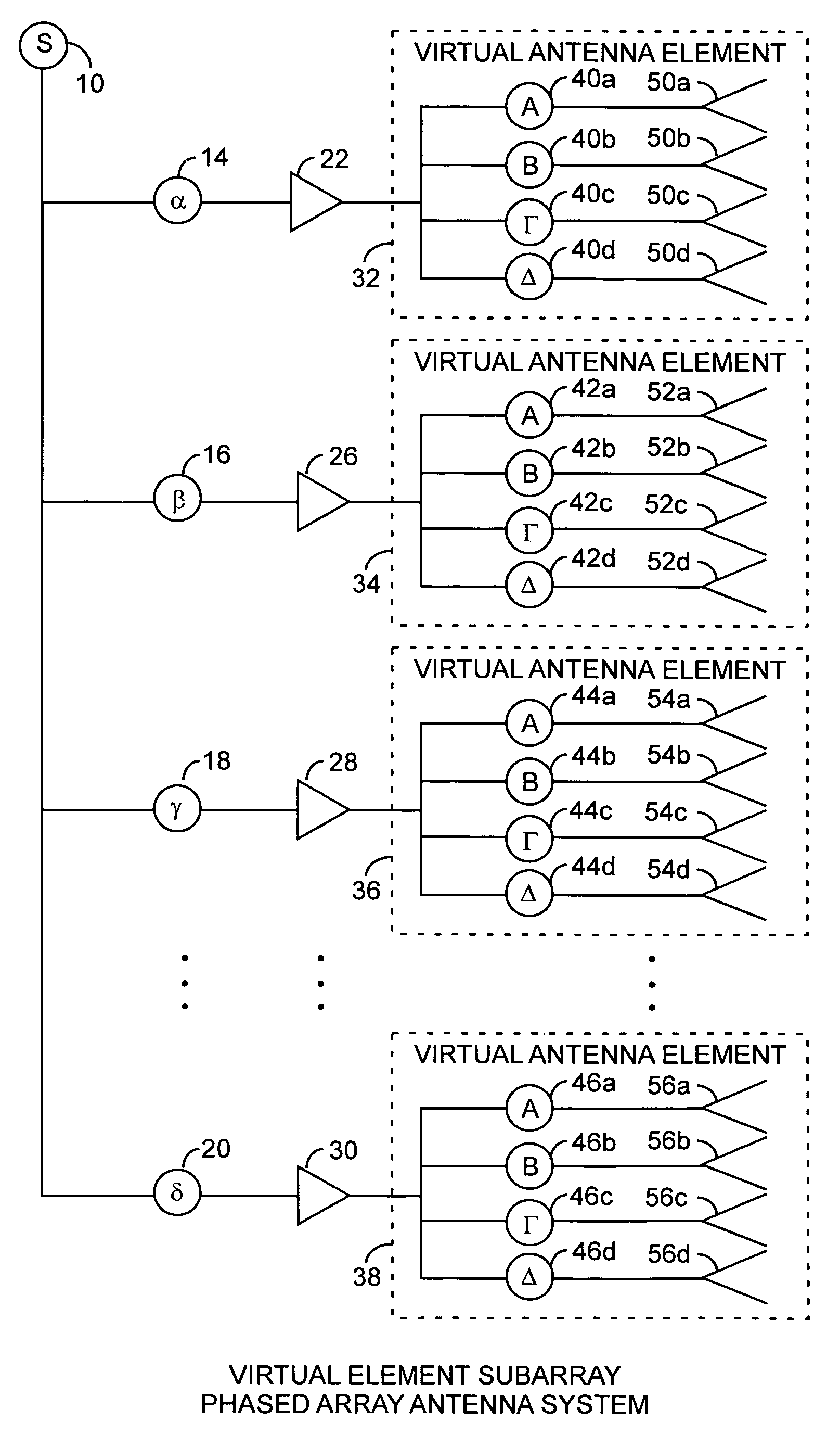
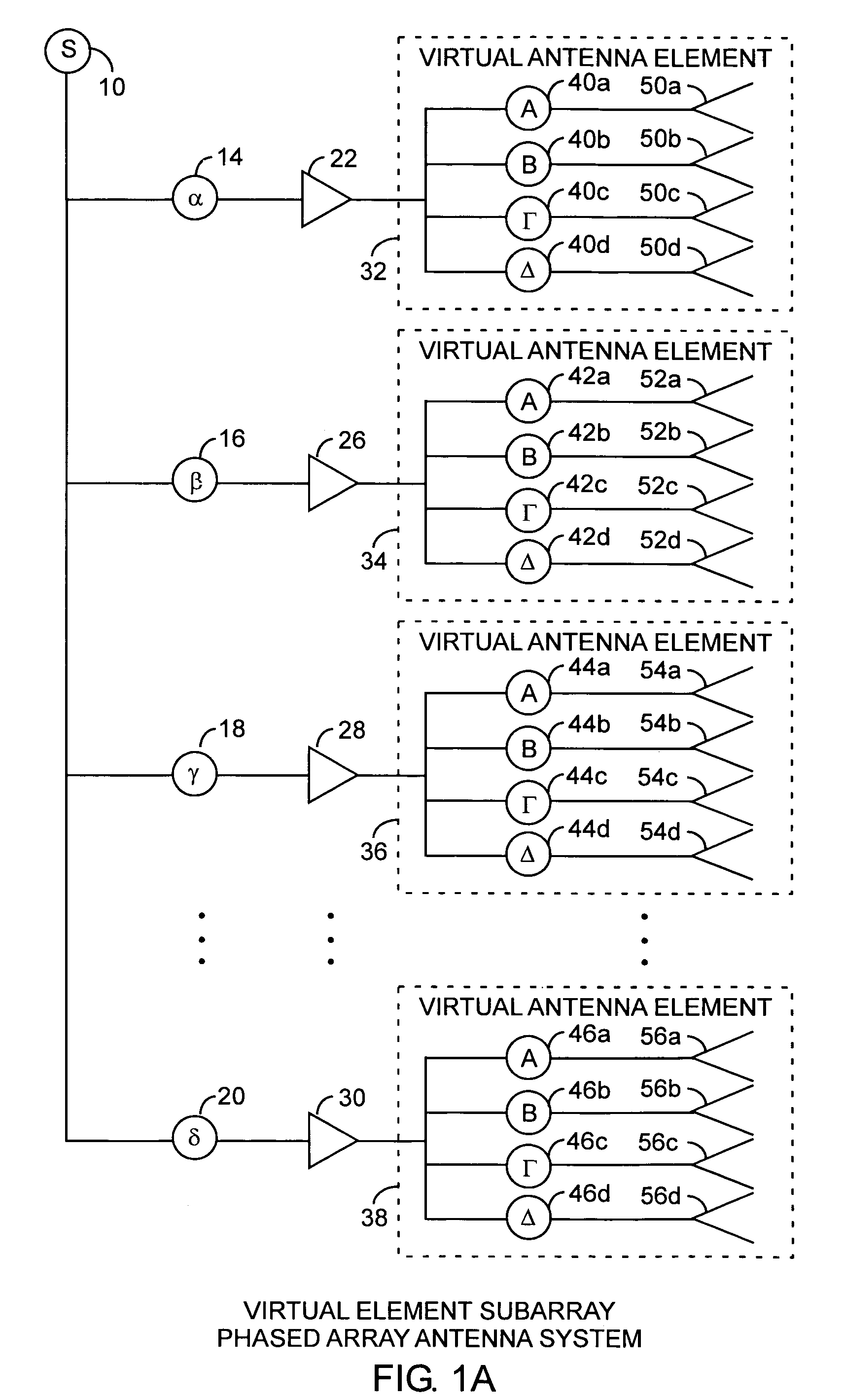
[0016]An embodiment of the invention is described with reference to the figures using reference designations as shown in the figures. Referring to FIG. 1A, a phase array antenna system transmits or receives a signal S. During transmission, the signal S is routed to four fine phase shifters 14, 16, 18, and 20 providing respective phase shifts α, β, γ, and δ, respectively. Each of the fine phase shifters 14, 16, 18, and 20 communicate the transmit signal 10 to amplifiers 22, 26, 28, and 30, that communicate an amplified and phase shifted signal respective to four virtual antenna elements 32, 34, 36 and 38. Each of the virtual antenna elements 32, 34, 36 and 38 include four coarse phase shifters, 40a, 40b, 40c, and 40d, and 42a, 42b, 42c, and 42d, and 44a, 44b, 44c, and 44d, and 46a, 46b, 46c, and 46d, respectively, and respective antenna elements 50a, 50b, 50c, and 50d, and 52a, 52b, 52c, and 52d, and 54a, 54b, 54c, and 54d, and 56a, 56b, 56c, and 56d, respectively. The coarse phase s...


PUM


Abstract

A phased array antenna system divides the array into a plurality of subarrays that are driven by fine phase shifters with each subarray having a plurality of antenna elements driven by respective coarse phase shifters that are preferably MEMS coarse phase shifters having low weight and low cost and are infrequently used for improved reliability for selecting a coarse beam coverage area while the fine phase shifters are used to scan a high-gain antenna pattern within the selected coarse beam coverage area. Two-bit MEMS phase shifters are used to scan the beams from subarrays to various coverage areas within the required antenna field of view, thereby providing coarse beam steering for an array.

Description

STATEMENT OF GOVERNMENT INTEREST[0001]The invention was made with Government support under contract No. FA8802-04-C-0001 by the Department of the Air Force. The Government has certain rights in the invention.FIELD OF THE INVENTION[0002]The invention relates to the field of antenna systems. More particularly the present invention relates to steered subarrays for multiple beam array antenna communication systems.BACKGROUND OF THE INVENTION[0003]The conventional phased array antenna systems utilize one discrete Gallium Arsenide field effect transistor (GaAs FET) phase shifter and a respective amplifier or transmit and receive transceiver for each respective radiating antenna element. The amplifiers are respectively positioned between the respective phase shifters and the respective antenna elements. The phase shifters are used for beam steering. However, conventional discrete FET phase shifters used for antenna beam steering are costly and have undesirable high insertion loss, especial...

Claims


Application Information

Patent Timeline
IPC IPC(8): H01Q3/24
CPCH01Q21/0006H01Q3/26
Inventor KSIENSKI, DAVID A.MCKAY, JAMES P.
Owner THE AEROSPACE CORPORATION
Why Eureka
Try Eureka