
Acoustic sensor for monitoring machining processes in machining tools

a technology of machining process and acoustic sensor, which is applied in the field of acoustic sensors, can solve the problems of poor performance in consideration of the limited frequency range, the difficulty of detecting said contact, and the difficulty of checking the machining process performed by an acoustic sensor operating in the said frequency rang

Inactive Publication Date: 2006-06-27
MARPOSS SPA
View PDF15 Cites 10 Cited by
  • Summary
  • Abstract
  • Description
  • Claims
  • Application Information

AI Technical Summary

Problems solved by technology

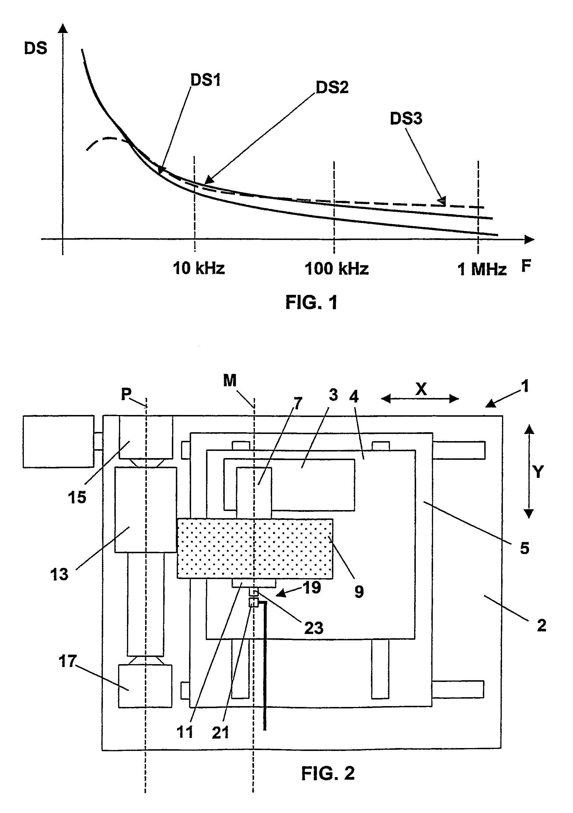
The use of high speed electrospindles generates an acoustic background noise that, in the frequency range utilized by the known acoustic sensors (50–250 KHz), is added to the acoustic signal generated by the occurrence of contact between the grinding wheel and the workpiece or the dressing wheel thus making the detecting of said contact extremely difficult.
As a consequence, the checking of the machining process, performed by an acoustic sensor operating in said range of frequencies, is extremely problematic.
EP-A-0446849 have poor performances in consideration of the limited range of frequencies within which there is guaranteed good response.

Method used


Image

  • Acoustic sensor for monitoring machining processes in machining tools
  • Acoustic sensor for monitoring machining processes in machining tools
  • Acoustic sensor for monitoring machining processes in machining tools

Examples


Embodiment Construction

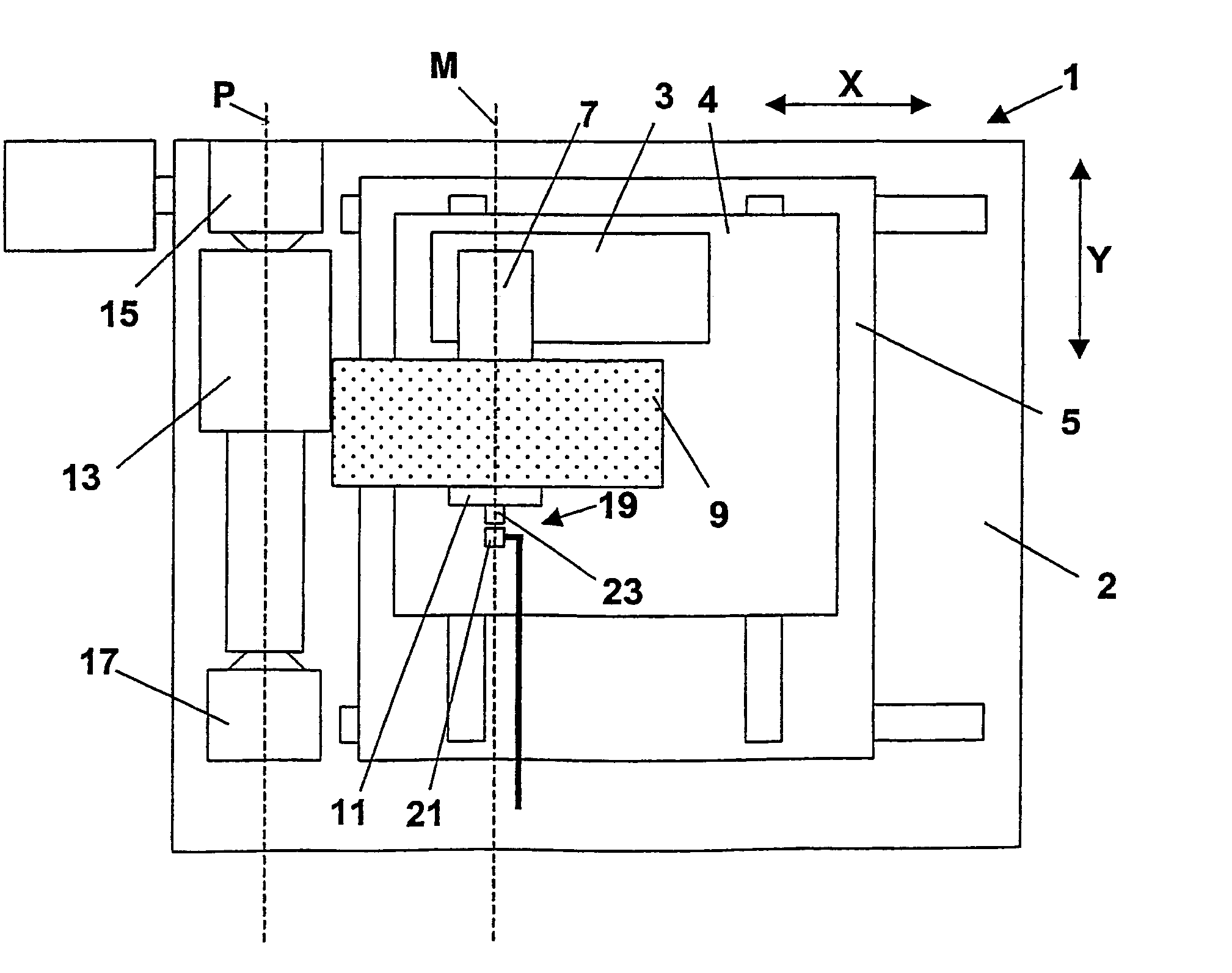
[0019]FIG. 2 is an extremely simplified and partial plan view of a machine tool, more specifically a computer numerical control (“CNC”) grinding machine 1 including a bed 2, a tool-carrier 3, more specifically a wheel-carrier, coupled to a slide 4, that can displace relative to bed 2 along an axis Y and is, on its turn, coupled to a slide 5 that can displace relative to bed 2 along an axis X, in such a way that the tool-carrier 3 can perform movements in plane XY relative to bed 2. A spindle, for instance an electrospindle 7, is carried by the tool-carrier 3 and a grinding wheel 9 is coupled, by means of a flange 11, to the electrospindle 7. The electrospindle 7 causes the grinding wheel 9 to rotate about a longitudinal axis M.

[0020]The grinding machine 1 is utilized for the machining of a mechanical piece 13, with rotational symmetry, for example a shaft, supported, referenced and made to rotate about a longitudinal axis P, parallel to the longitudinal axis M, by means of a support...


PUM

PropertyMeasurementUnit
shapeaaaaaaaaaa
elasticaaaaaaaaaa
cylindrical shapeaaaaaaaaaa

Abstract

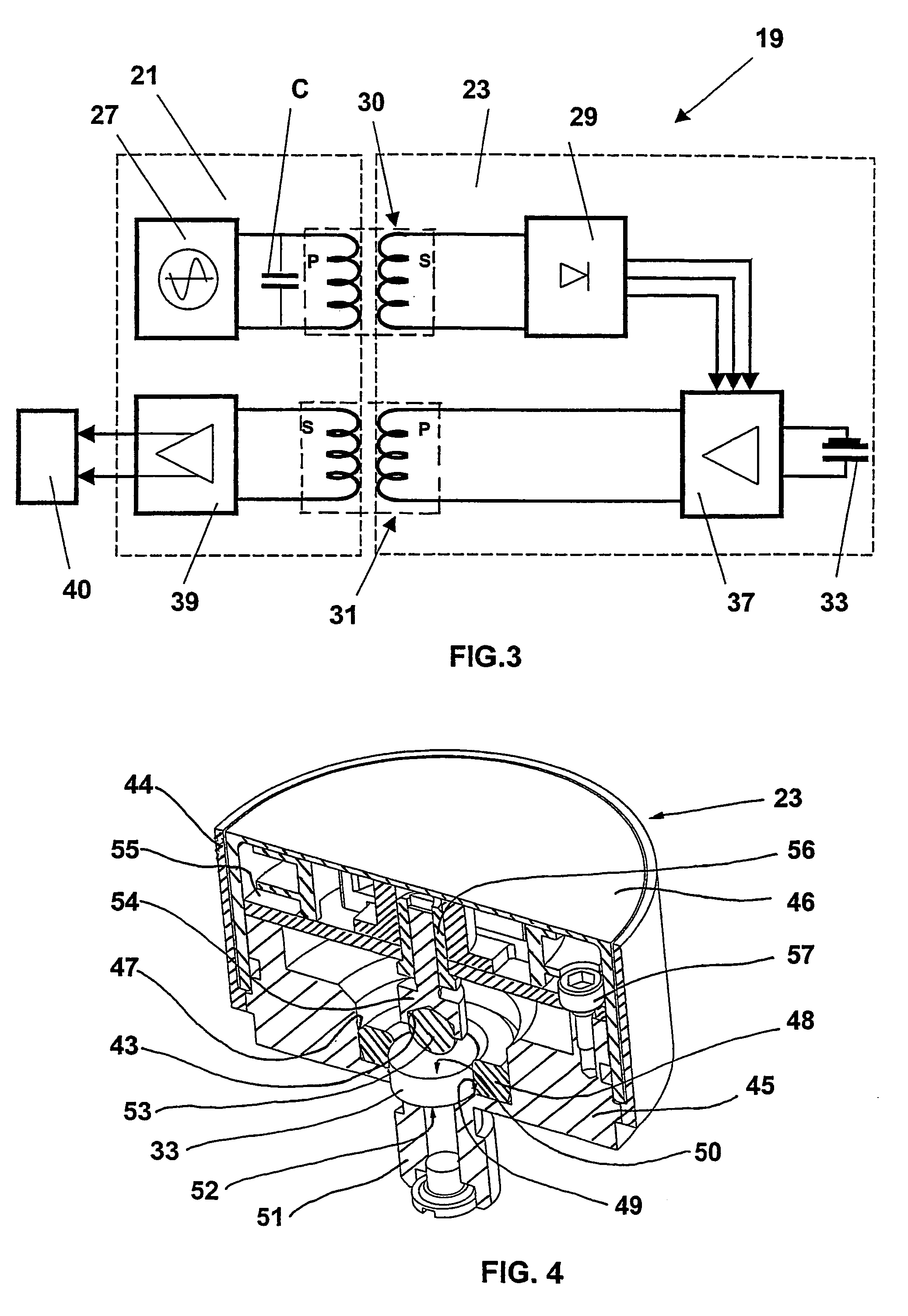
An acoustic sensor for monitoring machining processes in machining tools, e.g. grinding machines, includes a stationary unit, or stator (21) and a rotating unit, or rotor (23), the latter being coupled, for instance, to the grinding wheel and rotating with it. The rotor includes a support (45;45′) and a piezoelectric transducer (33). The position of the transducer is defined and locked without using glues by means of mechanical elements (48, 53, 54; 63, 64; 74, 78) that may include elastic elements such as springs. The rotor also includes a printed circuit board (55), connected to the piezoelectric transducer, with a charge amplifier (37) for amplifying the output signal of the piezoelectric transducer. The rotor is electrically coupled to the stator by means of transformer type couplings (30, 31).

Description

TECHNICAL FIELD[0001]The present invention relates to an acoustic sensor including a stationary unit, a rotating unit with support and protection elements with a support, a vibration detecting transducer coupled to the support, positioning and clamping elements adapted to define and lock the position of the transducer, and power supply, processing and transmission circuits with at least one contactless coupling adapted for achieving the electric connection between the stationary unit and the rotating unit.BACKGROUND ART[0002]Acoustic sensors are known and used, for example, in apparatuses for monitoring the machining process of computer numerical control (“CNC”) machine tools, as lathes, grinding machines, milling machines, etc. such apparatuses are able to detect, by means of sensors, the magnitude of physical features connected to the process to be checked, for example the wear of the tool, and indicate to the machine numerical control, or directly to the operator, the need to per...

Claims


Application Information

Patent Timeline
Patent Type & Authority Patents(United States)
IPC IPC(8): G01N29/00G01H17/00B23Q17/00B23Q17/09B24B49/10G01H1/00G01H11/08
CPCB23Q17/09G01H1/003B24B49/10B23Q17/098
Inventor DONDI, VALERIO
Owner MARPOSS SPA
Learn More