Life counter for flywheel energy storage systems

a technology of energy storage system and life counter, which is applied in the direction of mechanical roughness/irregularity measurement, machines/engines, and using mechanical means, etc., can solve the problems of composite materials can also experience stress rupture failure, and high stress level of flywheel operation, etc., to achieve higher performance operation, reduce the cost and complexity of flywheel system, and increase safety and reliability

Inactive Publication Date: 2006-06-27
VYCON ENERGY INC
View PDF14 Cites 14 Cited by
  • Summary
  • Abstract
  • Description
  • Claims
  • Application Information

AI Technical Summary

Benefits of technology

[0010]Compared with health measurement systems that use sensors to monitor for symptoms of failure of a flywheel system, the invention provides a reliable process and apparatus for determining when the flywheel system should be safely removed from service prior to a failure. This is particularly important because some failure modes may not have detectable symptoms or warning signs prior to complete failure. Use of the life counter requires a good understanding and analysis of the flywheel system components and their operating lives. However, the invention can provide increased safety and reliability and allow for higher performance operation. It can also reduce the flywheel system costs and complexity by reducing or eliminating the number of health measurement sensors and monitoring systems. Such sensors include thermocouples, vibrational sensors, vacuum gauges and load cells.

Problems solved by technology

Flywheels operate at high stress levels in operation and are subject to failure after continued cycling between the normal, fully charged operating speed and a lower speed when the flywheel system is discharged to some degree.
For composite material flywheels, the composite materials can also experience failure from stress rupture, which is time under load even without cycling.

Method used


Image

  • Life counter for flywheel energy storage systems
  • Life counter for flywheel energy storage systems
  • Life counter for flywheel energy storage systems

Examples


Embodiment Construction

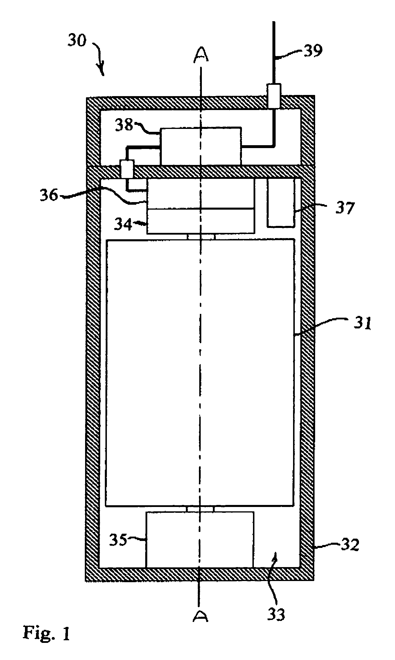
[0021]Turning now to the drawings, wherein like reference numerals designate identical or corresponding parts, and more particularly to FIG. 1 thereof, a flywheel energy storage system 30 is shown having a flywheel 31, constructed from metals such as high strength steel or alternatively from composite materials, that stores energy kinetically in rotational inertia and is supported for rotation about a vertical axis in a chamber 33 in a sealed container 32 that is evacuated for reduction of aerodynamic drag. The flywheel 31 is supported for rotation by a bearing system comprised of upper and lower bearings 34 and 35, which can be mechanical, such as ball bearings, magnetic or a combination. The bearings 34, 35 preferably support the flywheel 31 for a long reliable operating life with low losses. A motor / generator 36 is attached or made integral with the flywheel 31 for accelerating and decelerating the flywheel 31 for storing and retrieving energy. The power to and from the motor / gen...


PUM


Abstract

A life counter that calculates and records the life utilized of the flywheel in a flywheel energy storage system and indicates when it should be removed from service, based on operational history instead of monitoring for symptoms of failure. The life counter can effectively monitor and measure any or all of the flywheel energy storage system parameters, such as the flywheel structural life, vacuum system life, bearing system life and electronics life. The life counter ensures safe operation of highly stressed flywheels by indicating when the safety margin for the flywheel is reached so that the flywheel energy storage system can be removal from service prior to encountering a risk of catastrophic failure. In some cases, failures may not be preceded by measurable warning symptoms, so removal from service at a calculated end of life would be desirable. The life counter can indicate that the flywheel system should be removed from service by several methods that include triggering an alarm, displaying a reading, altering operation or stopping operation. The life can be indicative of the flywheel structural life, as adjusted by a suitable safety factor, or electronics high power cycle life.

Description

[0001]This is related to U.S. Provisional Application No. 60 / 342,423 filed on Dec. 21, 2001, and entitled “Life Cycle Counter for Energy Storage Flywheels”.[0002]This invention pertains to a life counter for flywheel energy storage systems, and more particularly to a life counter that calculates and records the life utilized of the flywheel energy storage system and indicates when it should be removed from service. Unlike a simple health measurement monitoring system, the life counter calculates and records life utilized based on the operational history, allowing for increased safety and reliability and higher performance operation. The life counter can be utilized for parameters including flywheel structural life, vacuum system life, bearing system life and electronics life. The invention is particularly useful for ensuring safe operation by indicating the structural life utilized of highly stressed flywheels. The life counter indicates when the safety margin for the flywheel or ot...

Claims


Application Information

Patent Timeline
Patent Type & Authority Patents(United States)
IPC IPC(8): H02K7/02
CPCB60L11/16Y02T10/7033Y02T10/7027Y10T74/2117Y10T74/2127B60L50/30Y02T10/70
Inventor GABRYS, CHRISTOPHER WCAMPBELL, DAVID R.
Owner VYCON ENERGY INC
Why Eureka
Try Eureka