Wind driven power generating system

a power generation system and wind technology, applied in the direction of wind energy generation, wind motors with parallel air flow, liquid fuel engine components, etc., can solve the problems of difficult blade fabrication, easy yaw operation, and inability to easily cool and maintain/repair, so as to avoid the overload of the generator, avoid the effect of overload and continuous generation of electricity

Inactive Publication Date: 2006-06-27
KIM DONG YONG +1
View PDF11 Cites 31 Cited by
  • Summary
  • Abstract
  • Description
  • Claims
  • Application Information

AI Technical Summary

Benefits of technology

[0012]Therefore, the present invention has been made in view of the above problems occurring in the prior art, and it is an object of the present invention to provide a wind driven power generating system in which, during the blowing of a strong wind, the rotating blade is automatically and variably slanted backwards by means of a spring force without any pitch control while directing against the wind, thereby protecting the system from overload of the power generator and continuing the generation of electricity.
[0014]According to the present invention, in response to a high wind pressure such as a strong wind or a sudden gust of wind, the blade variation unit is automatically operated such that the blade is variably slanted backwards and forwards to accommodate the high wind pressure without any additional pitch control. Therefore, the rotating power transmitted to the power generator can be controlled, thereby avoiding the overload of the generator, thus protecting the whole generating system, and also allowing for a continual generation of electricity even during a strong wind or a sudden gust of wind.
[0015]In addition, the power generator is placed in the tower and operably connected, via the vertical shaft, the bevel gears and the like, to the rotating blade mounted in the aerodynamic unit. Therefore, it allows for a convenient maintenance and an easy installation of electric wires, a stable yaw operation at a low speed of wind due to the lightness of the aerodynamic unit, and prevention of wire twisting during the rotation of the aerodynamic unit.
[0016]Furthermore, the simplified structure of the wind driven power generating system of the invention makes it possible to reduce the manufacturing cost thereof.

Problems solved by technology

However, the main body with the power generator and the like equipped therein is heavy to the extent that it disturbs an easy yaw operation depending on the wind direction.
In addition, since the power generator is placed inside the main body, it cannot readily be cooled and maintained / repaired.
However, the opposite rotating directions of the main and auxiliary blades make it difficult to fabricate the blades, and a precision pitch control must be carried out with respect to each blade in order to uniformly combine the torque of the main and auxiliary blades, but practically a perfect pitch control cannot be easily achieved.
Furthermore, similar to the horizontal type generating system, the manufacturing cost is rather high, and at emergency such as a strong wind the generation of electricity cannot be continued.

Method used


Image

  • Wind driven power generating system
  • Wind driven power generating system
  • Wind driven power generating system

Examples


Embodiment Construction

[0024]Reference will now made in detail to the preferred embodiment of the present invention with reference to the attached drawings. It is noted that details on the well-known components and their functions will not be described.

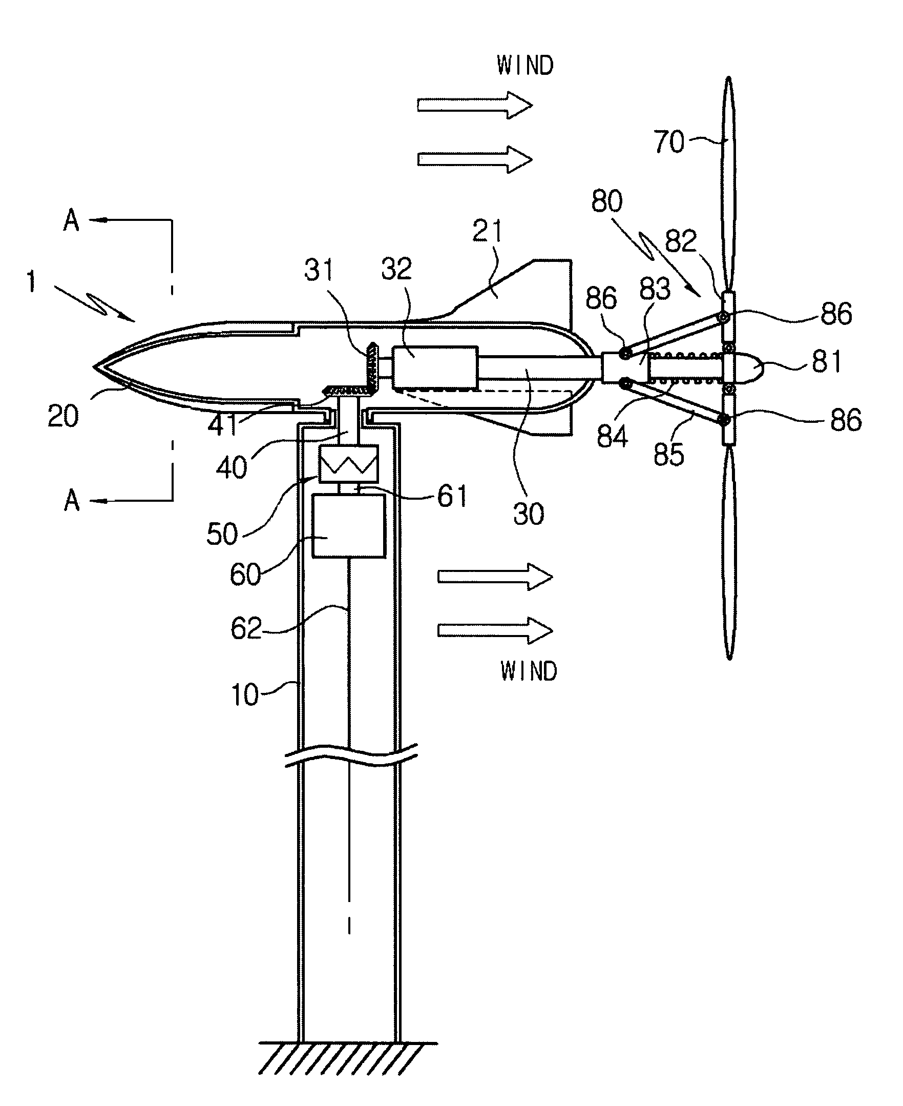
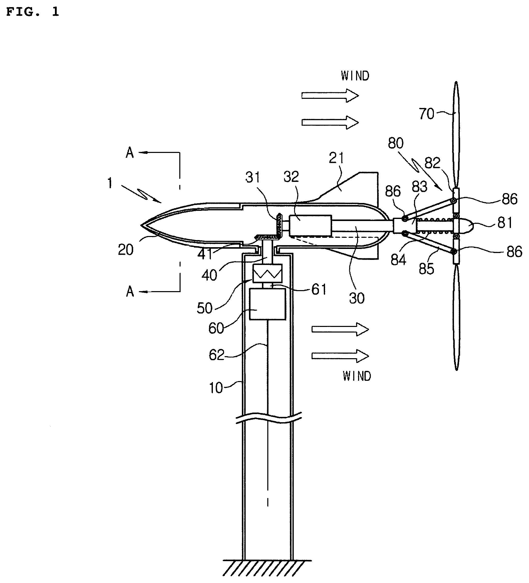
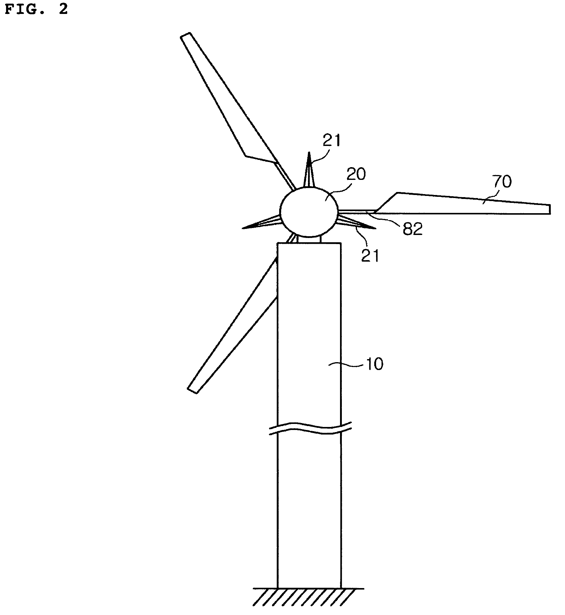
[0025]FIG. 1 illustrates a cross sectional view of a wind driven power generating according to one embodiment of the invention, in which the wind driven power generating system is generally denoted at reference numeral 1. FIG. 2 is a front view of the wind driven power generating system in FIG. 1, and FIG. 3 illustrates details of a blade variation device and its operation according to one embodiment of the invention.

[0026]Referring to FIGS. 1 to 3, the wind driven power generating system 1 includes a tower 10 having a certain height and secured to the ground, and an aerodynamic unit 20 rotatably mounted atop the tower 10.

[0027]The inside of the aerodynamic unit 20 is preferred to be hollow to make it light.

[0028]A rudder 21 is radially formed on the outer ...


PUM


Abstract

The present invention discloses a wind driven power generator. The wind driven power generating system comprises: a) an aerodynamic unit rotatably mounted at the top of a tower having a certain height; b) a plurality of rudders for aligning the aerodynamic unit with the direction of wind, the rudders being radially formed on the outer surface of the aerodynamic unit; c) a horizontal shaft rotatably and horizontally mounted in the aerodynamic unit, wherein one end of the outwardly from the backend of the aerodynamic unit and the other end of the horizontal shaft remains inside of the aerodynamic unit and is provided with a first bevel gear; d) a blade attached to the rear end of the horizontal shaft, wherein the blade is rotated by the wind and thus rotates the horizontal shaft; e) blade variation means disposed at the rear portion of the aerodynamic unit for slanting the blade backwards and forwards, depending on the wind pressure; f) a power generator installed inside the tower; and g) a vertical shaft for transmitting the rotating power of the horizontal shaft to the power generator, wherein one end of the vertical shaft is provided with a second bevel gear, which is engaged with the first bevel gear, and the other end thereof is connected to a rotor shaft of the power generator.

Description

BACKGROUND OF THE INVENTION[0001]1. Field of the Invention[0002]The present invention relates to a wind driven power generating system of single rotor type in which a horizontal and vertical shafts are combined. Specifically, the invention relates to a wind driven power generating system in which, under blowing of strong wind, the rotating blade is automatically and variably slanted backwards by means of a spring force without any pitch control while directing against the wind, thereby protecting the system and continuing the generation of electricity.[0003]2. Background of the Related Art[0004]In general, a wind driven power generating system generates electricity by using a blade driven by the wind power. That is, the kinetic energy due to rotation of the blade is converted into electrical energy, which is supplied to individual users. The conventional wind driven power generating system, according to the orientation of shafts, is categorized into a horizontal shaft system having ...

Claims


Application Information

Patent Timeline
Patent Type & Authority Patents(United States)
IPC IPC(8): F04D7/04F01D7/02F03D7/04B63H1/06F03D1/06F03D5/00F03D9/00F03D11/04
CPCF03D1/0658F03D11/02F03D7/0236Y02E10/722F05B2240/2022F05B2240/2213F05B2250/192F05B2250/232F05B2260/4031F05B2260/502F05B2260/78F05B2260/79Y02E10/721Y02E10/723Y02E10/725Y10S415/908F03D15/00F03D15/10F03D9/25Y02E10/72E21D11/383E21D11/381E02D31/025E02D2450/105
Inventor KIM, DONG YONGKIM, YEONG MIN
Owner KIM DONG YONG
Why Eureka
Try Eureka