
Selective photothermolysis

a selective photothermolysis and apparatus technology, applied in the field of apparatus and a selective photothermolysis, can solve the problems of scarring of surrounding tissue, increased risk of healthy tissue damage, etc., and achieve the effect of preventing healthy tissue surrounding

Inactive Publication Date: 2006-06-27
RADIANCY
View PDF23 Cites 76 Cited by
  • Summary
  • Abstract
  • Description
  • Claims
  • Application Information

AI Technical Summary

Benefits of technology

[0024]Additionally, in conjunction with the multiple beams operating at the target optionally the skin may be cooled, to further avoid overheating of the skin; such cooling enables the use of beams with higher heat producing content.
[0035]In a preferred embodiment of the invention, the apparatus includes a cooling unit suitably attached to said housing and controlled by said controller for controllably cooling surrounding tissue, to augmentally prevent healthy tissue surrounding the tissue disorder from overheating. Preferably, the cooling unit is activated by said controller when said skin has reached a predetermined temperature after said heat source is energized.
[0036]There is thus provided, in accordance with a preferred embodiment of the invention, apparatus for selective photothermolysis of sub-cutaneous target tissue, the apparatus comprising a plurality of beams of narrow band electromagnetic radiation, each of the beams having energy that is insufficient to heat tissue upon which is falls to a temperature high enough for tissue damage; and a beam director directing said beams to substantially overlap beneath the skin at a target, said combination of light beams due to the overlapping being capable of causing the target area to heat sufficiently to cause tissue damage; thus destroying the cause of skin disorders. Preferably, the beam director directs the beams to overlap substantially simultaneously. Alternatively or additionally the beams are caused to overlap substantially sequentially. In a preferred embodiment of the invention, the narrow band electromagnetic radiation is a monochromatic light. Preferably, the plurality of beams of light is produced by at least a single source. Alternatively or additionally, the light is produced by a plurality of light sources. Preferably, the apparatus, includes pulsing apparatus for providing pulses of said light. In a preferred embodiment of the invention the light is laser light. Preferably, the laser light has a wavelength in the range of 550-800 nanometers. Alternatively, the light is provided by a flash-lamp providing pulses of light or alternatively, the monochromatic light is derived from filtering broad band light with a narrow band filter. Preferably, a plurality of light sources are provided. In a preferred embodiment of the invention, a cooling device for cooling tissue surrounding the target area during and / or after the photothermolysis is provided. Preferably, the cooling device comprises a housing for said light, said housing sealing said target area and surrounding tissue, and pump means for replacing warmed air in said housing with cooler air. In a preferred embodiment of the invention, the apparatus includes at least a temperature monitor monitoring the temperature of air in said housing. Additionally or alternatively, at least a temperature monitor monitoring the temperature of the surrounding tissue is provided. Alternatively or additionally, at least a temperature monitor for monitoring the temperature of the target is provided. In a preferred embodiment of the invention, the apparatus includes control apparatus for controlling the applications of the electromagnetic light responsive to monitored temperatures. Preferably, the control apparatus controls the application time and heat content of the light responsive to the monitored temperatures.

Problems solved by technology

A complication arises in the treatment of varicose veins by selective photothermolysis.
The damage to the surrounding tissue may include scarring.
The problem is the prevention of damage to the surrounding healthy tissue.
The absorption of laser energy by the melanin causes localized heating in the epidermis and reduces the light dosage reaching the target thereby decreasing the quantity of heat in the targeted area, leading to sub-optimal blanching of the tissue disorder or necessitating increased time periods of treatment with consequent increased risk of healthy tissue damage, unless steps are taken to protect the healthy tissue.

Method used


Image

  • Selective photothermolysis
  • Selective photothermolysis
  • Selective photothermolysis

Examples


Embodiment Construction

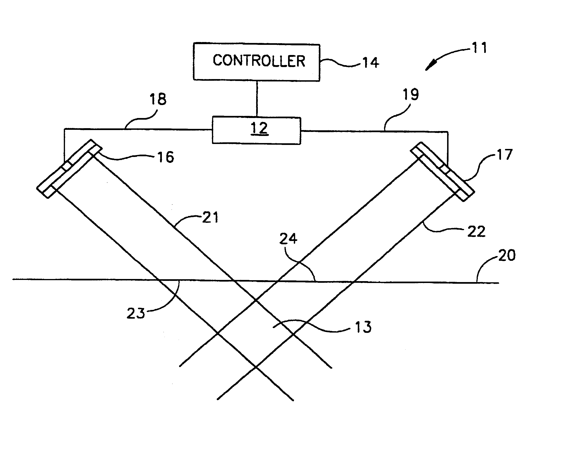
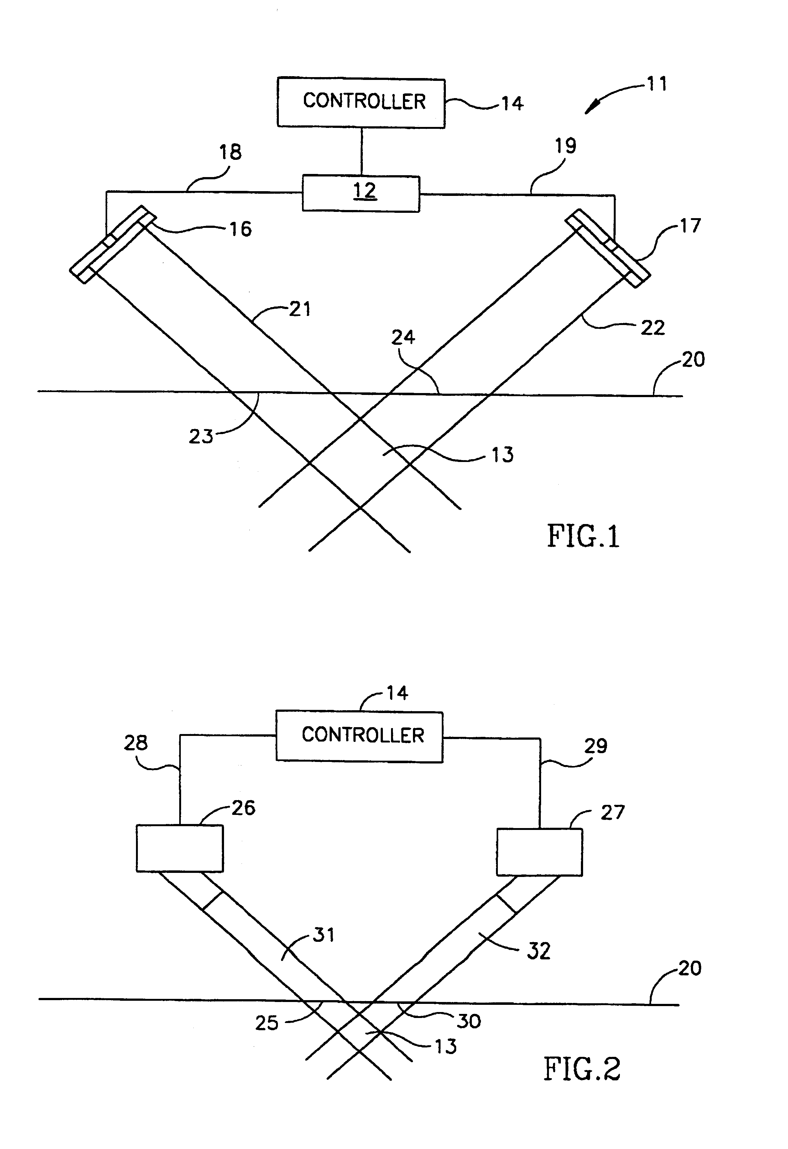
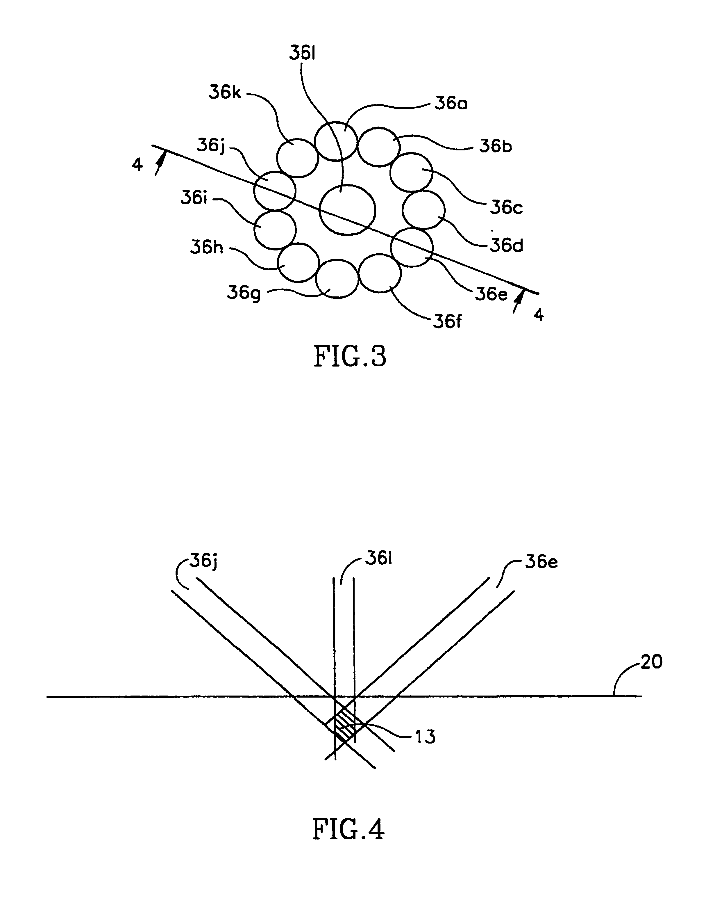
[0045]An aspect of the present invention is a method and device for selective photothermolysis of various sized targets. Specifically, the present invention can be used to remove varicose veins and or port wine stains, psoriasis and similar unsightly tissue with equal facility and with minimal damage to the surrounding healthy tissue.

[0046]Referring now to the drawings, FIG. 1 is a schematic diagram of a basic preferred embodiment of the present invention. There is shown in FIG. 1 a system 11 which comprises a single source of monochromatic light 12. Preferably, the monochromatic light source provides a laser beam. Alternatively, the source could be the source of broad-band (white) light operated in conjunction with a filter (not shown) to filter out all of the white light, except for the desired monochromatic light. The monochromatic light, preferably, is at a wavelength of between 550-800 nanometers, directed at a target 13 through the epidermis and surrounding tissue.

[0047]A cont...


PUM


Abstract

Performing selective photothermolysis of sub-cutaneous tissue by using a plurality of beams of narrow band electro-magnetic radiation, where each of the beams have energy that is insufficient to heat the tissue that they strike to a temperature high enough to destroy such tissue, but by directing the individual beams to overlap at the target sufficient heat is generated to destroy the target tissue.

Description

RELATED APPLICATIONS[0001]This application is a U.S. national filing of PCT Application No. PCT / IL99 / 00658, filed Dec. 2, 1999.FIELD OF THE INVENTION[0002]The present invention relates to apparatus and a method of selective photothermolysis that allows the destruction of unsightly skin disorders, such as birthmarks, varicose veins, plaque psoriasis and others. According to the invention, the disorders are selectively destroyed without damaging the surrounding healthy tissue.BACKGROUND OF THE INVENTION[0003]Selective photothermolysis is a method, described by Anderson and Parrish in 1983 (“Selective Photothermolysis: Precise Microsurgery by Selective Absorption of Pulsed Radiation”, Science, Vol. 220, pp. 524-527), for destroying certain diseased or unsightly tissue, on or near the skin, with minimal damage to the surrounding healthy tissue. The tissue to be destroyed is generally characterized by significantly greater optical absorption at some wavelength of electromagnetic radiatio...

Claims


Application Information

Patent Timeline
IPC IPC(8): A61B18/18A61B17/00A61B18/00A61B18/20
CPCA61B18/203A61B18/20A61B2017/0007A61B2017/00084A61B2017/00088A61B2018/208A61B2018/00452A61B2018/00458A61B2018/00636A61B2018/1807A61B2018/00017
Inventor AZAR, ZIONSHALEV, PINCHAS
Owner RADIANCY
Learn More