

Resin-bond type optical element, production method therefor and optical article
a resin-bond type, optical element technology, applied in the field of resin-bond type optical element, production method therefor and optical article, can solve the problems of difficult materialization of required optical characteristics, difficulty in working, and insufficient wide application of aspheric lenses having such superior characteristics. achieve the effect of superior resin-cemented and high light transmittan
- Summary
- Abstract
- Description
- Claims
- Application Information
AI Technical Summary
Benefits of technology
Problems solved by technology
Method used
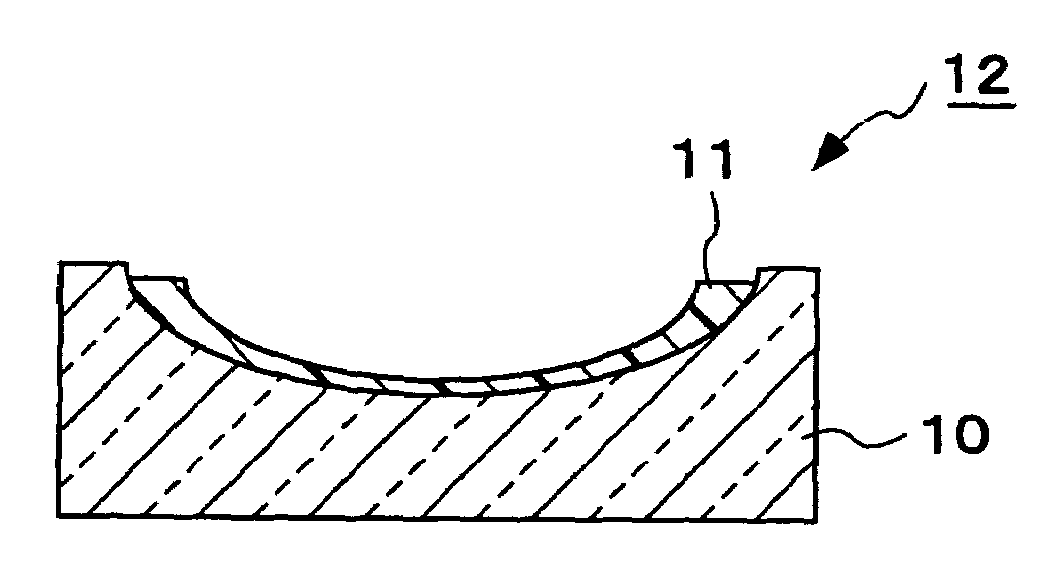
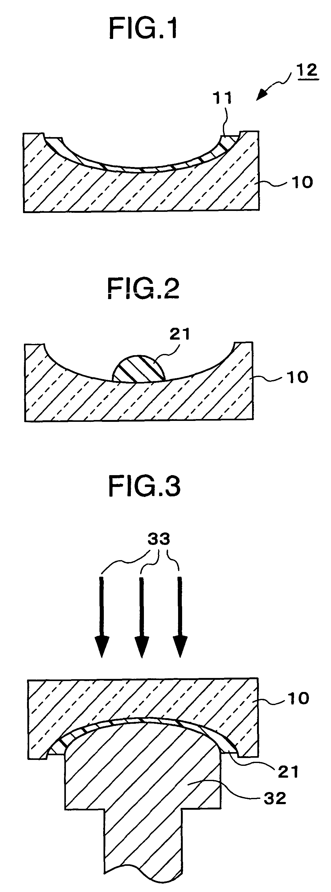
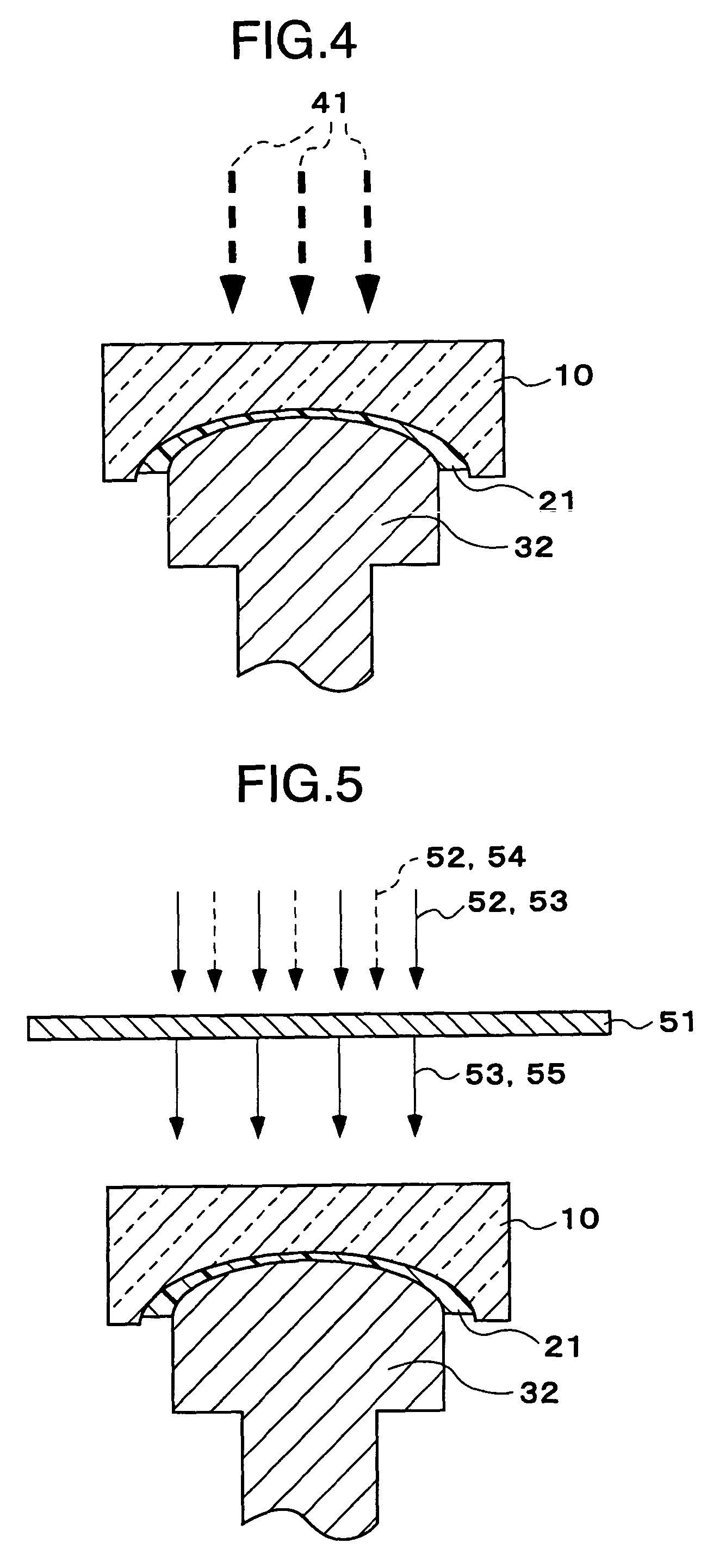
Image

Examples
example 1
[0133]In this Example, first a resin composition (photosensitive resin composition) was prepared which was obtained by mixing the following components (A) to (C). Next, this composition was coated on a glass base, followed by curing to form a resin layer to produce a PAG lens.
[0134]Component (A): 80 parts of di(meth)acrylate of Formula (1) wherein m+n is 3.
[0135]Component (B): 19.5 parts of urethane-modified di(meth)acrylate of Formula (2).
[0136]Component (C): 0.5 part of an acetophenone type photopolymerization initiator.
[0137]The refractive index of this resin composition before curing was 1.535, and the viscosity thereof at room temperature was 3,500 cP.
[0138]This resin composition was poured into a base mold made of glass, and then irradiated by light of a high-pressure mercury lamp for 2 minutes to form a rectangular colorless transparent block of 2 mm thick. Concerning this block, its refractive index after curing was measured to find that it was 1.556. Its durometer hardness ...
example 2
[0150]In this Example, a PAG lens was produced in the same manner as in Example 1 except that the urethane-modified hexa(meth)acrylate of Formula (3) was used as the component (B) of the resin composition.
[0151]Physical properties of the resin composition before curing and of the resin after curing which were measured in the same manner as in Example 1 are shown in Table 1.
[0152]
TABLE 1Example1234567Before curing:Refractive1.5351.5311.5321.5251.5291.5291.530indexViscosity at3500450020003000350035003500roomtemperature(cP)After curing:Refractive1.5561.5521.5561.5511.5551.5551.556indexDurometerHDD78HDD82HDD80HDD80HDD79HDD79HDD80hardnessTransmittance97989898989898(100 μmthicknessGlass9710110099100100100transitiontemperature(° C.)Hygroscopic0.350.300.350.300.350.350.35dimensionalchange (%)Gel97989898989898percentage(%)Shrinkage on5.56.06.05.06.06.06.0curing (%)
[0153]Next, a PAG lens was produced using an aspherical-surface metal mold in the same manner as in Example 1. As the result, the...
example 3
[0156]In this Example, a PAG lens was produced in the same manner as in Example 1 except that the urethane-modified tetra(meth)acrylate of Formula (4) was used as the component (B) of the resin composition. As the result, the desired aspherical shape had exactly been transferred to the resin layer without any coming-off of the resin from the mold during the molding. Physical properties of the resin composition before curing and of the resin after curing which were measured in the same manner as in Example 1 were as shown in Table 1.
[0157]On the surface of the resin layer thus obtained, a anti-reflection coat was further formed in the same manner as in Example 1. As the result, a PAG lens having both good external appearance and good performance was obtained, and the results of its heat resistance test were also as good as those in Example 1.
[0158]The same good results as those in Example 1 were also obtained in the weatherability test made using a carbon fadometer.
PUM
| Property | Measurement | Unit |
|---|---|---|
| refractive index | aaaaa | aaaaa |
| refractive index | aaaaa | aaaaa |
| refractive index | aaaaa | aaaaa |
Abstract
Description
Claims
Application Information