Device for inhibiting hydrogen damage in ferroelectric capacitor devices

a technology of ferroelectric capacitors and devices, which is applied in the direction of capacitors, semiconductor devices, electrical apparatus, etc., can solve the problems of serious degradation of the ferroelectric performance of the capacitor, sintering damage to the capacitor, and the inability to inhibit the hydrogen diffusion of the capacitor during processing, so as to avoid or reduce the damage to the capacitor during processing. , the effect of preventing the diffusion of hydrogen into the ferroelectric layer

Inactive Publication Date: 2006-07-04
QIMONDA
View PDF10 Cites 10 Cited by
  • Summary
  • Abstract
  • Description
  • Claims
  • Application Information

AI Technical Summary

Benefits of technology

[0007]In general terms, the present invention propose that one or more layers of hydrogen storage material be applied to the encapsulant and / or cover layers of the capacitor. By covering the encapsulant and / or cover layers with such a material, hydrogen diffusion into the ferroelectric layer can be inhibited. This is considered particularly advantageous as damage to the capacitor from hydrogen diffusion during processing may thereby be avoided or reduced.
[0016]Preferably, the device further comprises one or more second encapsulation layers formed on said one or more hydrogen storage material layers to provide further protection against hydrogen damage.

Problems solved by technology

Conventional integrated ferroelectric Random Access Memories (FeRAMs) including one or more of the above types of capacitors generally suffer from a number of problems.
These problems are predominantly due to hydrogen damage generated during the backend process of application of the intermetal dielectric layer and deposition of the encapsulation and / or cover layers.
Processes such as plasma-Tetraethyl Orthosilicate (p-TEOS) deposition which is used to apply the one or more interlayer dielectric layers to the capacitor, RIE (reactive ion etch), and sintering are known to damage the capacitor due to the reducing effects of the hydrogen released.
These types of effects can lead to serious degradation of the ferroelectric performance of the capacitor.
The damaged capacitors have more defects resulting in more space charge formation and their ferroelectric properties degrade.
Such conventional techniques have limited success as the encapsulant and cover layers are insufficient to prevent hydrogen diffusion.
Other attempts have been made to reduce the effect of hydrogen on the capacitor, for example, by burying or recessing the bottom electrode in the substrate, however, these have not been found to be effective in preventing hydrogen damage.

Method used


Image

  • Device for inhibiting hydrogen damage in ferroelectric capacitor devices
  • Device for inhibiting hydrogen damage in ferroelectric capacitor devices
  • Device for inhibiting hydrogen damage in ferroelectric capacitor devices

Examples


Embodiment Construction

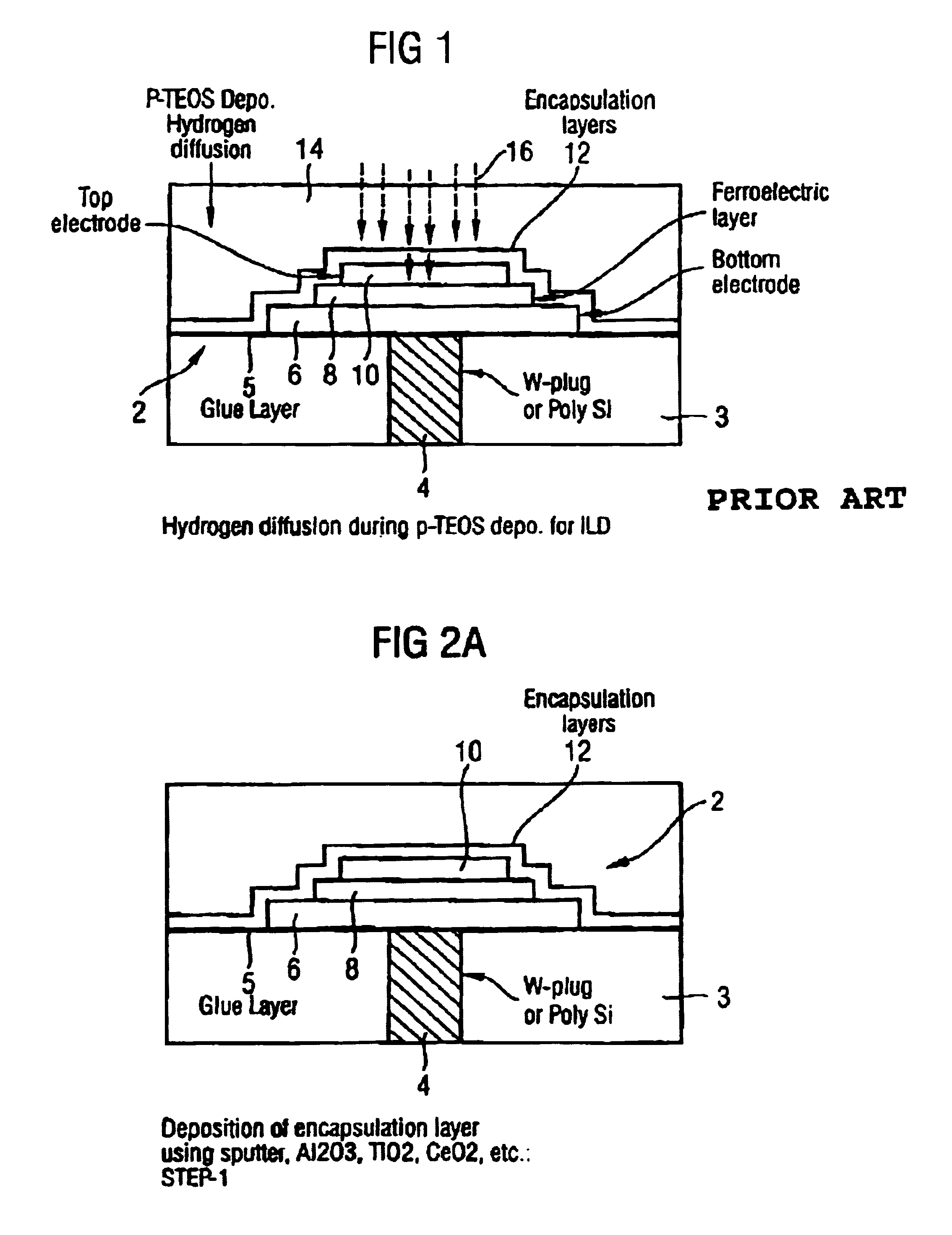
[0027]Conventional ferroelectric capacitors 2 such as that shown schematically in FIG. 1, comprise a substrate 3, a contact plug 4 extending through the substrate 3, a glue layer 5 applied to the substrate 3, a bottom electrode 6 on said glue layer 5, a ferroelectric layer 8 of material, such as PZT, on said bottom electrode 6, and a top electrode 10 on said ferroelectric layer 8. One or more encapsulation layers 12 cover the capacitor 2. The plug 4 may be formed of, for example, tungsten or polysilicon.

[0028]The capacitor is covered with one or more interlayer dielectric layers 14, normally plasma-Tetraethyl Orthosilicate (p-TEOS), and connection to the top electric is achieved by etching a window (not shown) through the interlayer dielectric layer(s) 14 and filling the window with a metal filler (not shown). During the deposition of the p-TEOS layer(s) 14, hydrogen ions 16 are released which diffuse through the encapsulation layer(s) 12, into the top electrode 10 and the ferroelec...


PUM


Abstract

A ferroelectric capacitor device comprises a substrate, a contact plug passing through the substrate, a first electrode formed on the substrate, the first electrode being electrically connected to said plug, a ferroelectric layer formed on the first electrode, a second electrode formed on the ferroelectric layer, one or more first encapsulation layers on the second electrode, the encapsulation layers extending over the device, and one or more hydrogen storage material layers on the encapsulation layers. One or more second encapsulation layers may be formed on the one or more hydrogen storage material layers.

Description

FIELD OF THE INVENTION[0001]The present invention relates to methods and systems for inhibiting hydrogen damage in, for example, ferroelectric capacitor devices.BACKGROUND OF THE INVENTION[0002]A conventional integrated ferroelectric capacitor includes one or more ferroelectric layers sandwiched between a bottom electrode and a top electrode. The ferroelectric layer(s) may include, for example, PZT, SBT or BLT. The capacitor is covered with one or more interlayer dielectric layers, normally Tetraethyl Orthosilicate (TEOS), and connection to the top electrode is achieved by etching a window through the interlayer dielectric layer(s) and filling the window with a metal filler. The bottom electrode is mounted on a substrate, the electrical connection to the bottom electrode being via a metal plug through the substrate. To make the connection between the bottom electrode and the plug, a window is formed through the interlayer dielectric layer(s), through the other layers of the capacito...

Claims


Application Information

Patent Timeline
Patent Type & Authority Patents(United States)
IPC IPC(8): H01L29/76H01L21/02H01L21/8246H01L27/08
CPCH01L27/0805H01L28/57H01L27/11507H10B53/30
Inventor MOON, BUM-KIHORNIK, KARLZHUANG, HAORENEGGER, ULRICHLIAN, JENNYHILLIGER, ANDREAS
Owner QIMONDA
Why Eureka
Try Eureka