Method and system for reducing bearing fluting in electromechanical machine

a technology of electromechanical machines and fluting, applied in the field of electromechanical machines, can solve the problems of affecting the operation of the machine, affecting the operation of the bearing unit, and causing the machine to produce a succinct shaft voltage, so as to reduce the chance of stray currents, and reduce the switching frequency of the converter

Inactive Publication Date: 2006-07-04
PRECOR
View PDF34 Cites 35 Cited by
  • Summary
  • Abstract
  • Description
  • Claims
  • Application Information

AI Technical Summary

Benefits of technology

[0009]The present invention consists of a novel combination of arrangements that are each designed to reduce the amount of stray currents passing through motor bearings or, more specifically, the current density of such currents. The combination generally includes two to five arrangements. First, an insulating ring of non-conductive material may be mounted in a motor bell to serve as both a support for the motor bearing and a barrier insulating the motor shaft and the motor bearing from the motor bell. The insulating ring reduces the chance of possible bearing failure caused by current passing through the motor bearings to the rotating shaft and vice versa. Alternatively, the insulating ring can be injection molded directly into the motor bell eliminating the need to machine the motor bell and press fit the insulating ring in t...

Problems solved by technology

When dealing with electromechanical machines, invariably, stray current generated in the field of the electromechanical machine will produce a succinct shaft voltage.
High shaft voltages produce damaging currents that are between the components of the motor bearings when the voltage reaches a critical level.
The bearing grease resident between the bearin...

Method used


Image

  • Method and system for reducing bearing fluting in electromechanical machine
  • Method and system for reducing bearing fluting in electromechanical machine
  • Method and system for reducing bearing fluting in electromechanical machine

Examples


Embodiment Construction

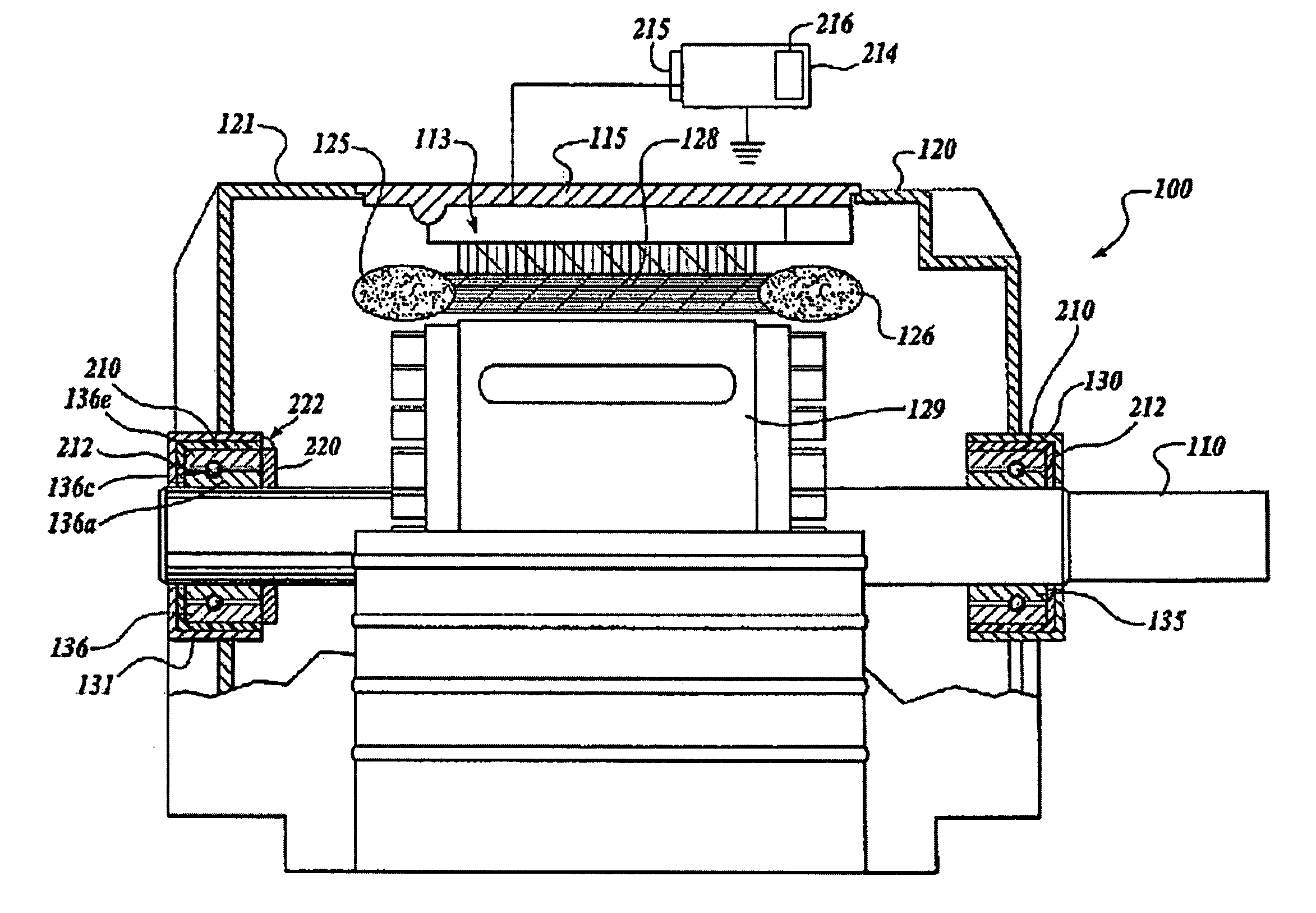
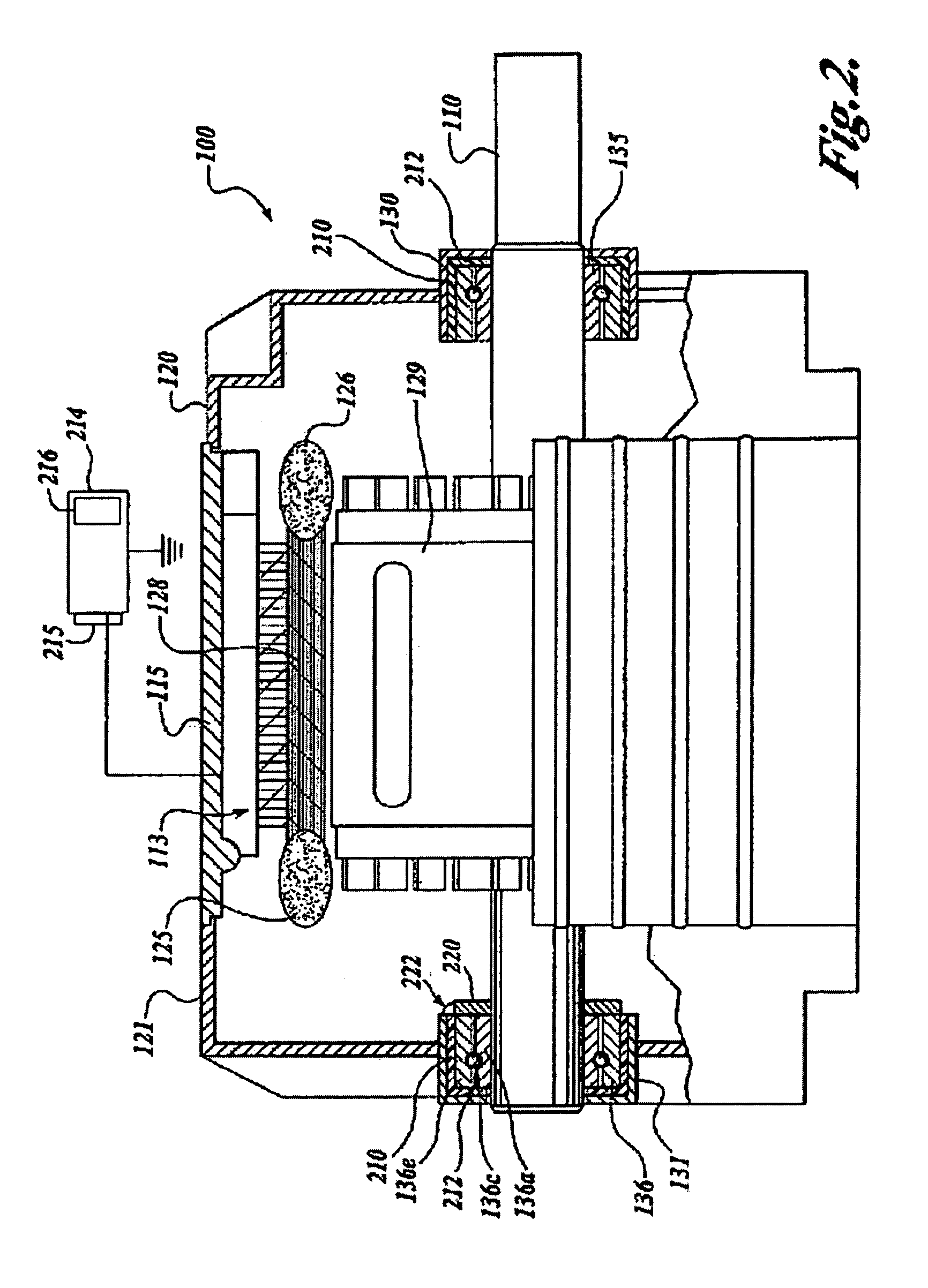
[0016]This invention relates generally to the field of electromechanical machines that have a rotating shaft, such as electric motors, and more specifically to a combination of various arrangements that are designed to prevent fluting or other damage as a result of stray currents travelling through motor bearings.

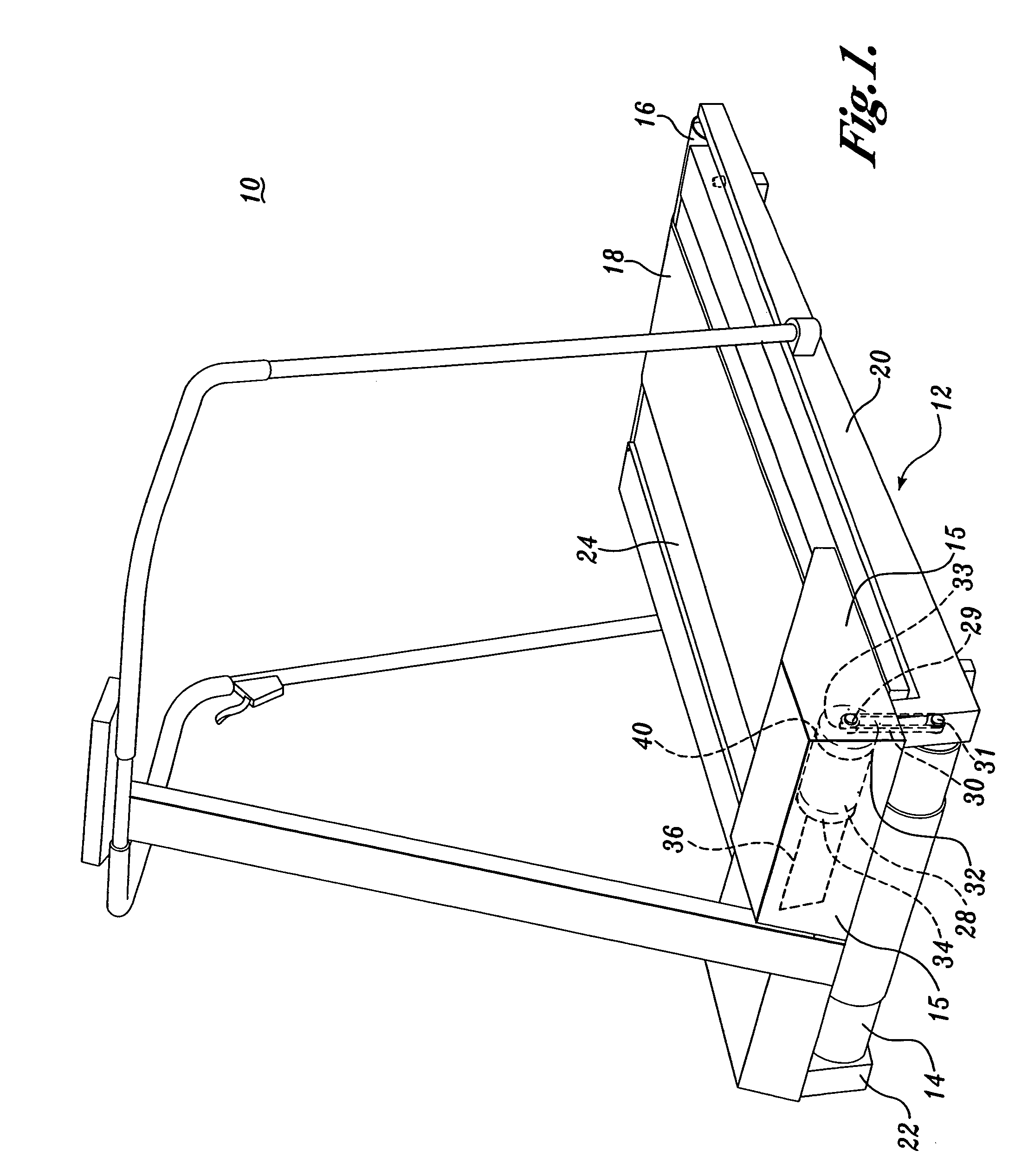
[0017]Electric motors that benefit greatly from the present invention are those used in exercise treadmills. FIG. 1 illustrates a typical exercise treadmill 10, which includes a longitudinal frame 12, on the opposite ends of which are transversely mounted a forward roller assembly 14 and a rear roller assembly 16. An endless belt 18 is trained about the forward roller assembly 14 and rear roller assembly 16. The treadmill frame includes first and second longitudinal rail members 20 and 22. The longitudinal rail members are spaced apart and joined by cross members (not shown), as is well known in the field of treadmill frame construction. A relatively rigid deck 24 spans bet...


PUM


Abstract

A non-conductive insulating ring (210) is inserted between a motor bell (130) and a motor bearing (135) that supports a motor shaft (110). Stray currents that normally discharge thorough the motor shaft and the motor bearing to the motor bell are prevented due to the non-conductive nature of the insulating ring. Additionally, the motor shaft is grounded to provide a low-impedance alternative path to stray shaft currents. When a fast-switching frequency converter is used to drive the motor shaft, additional arrangements such as a common mode choke, reduction of the switching frequency of the converter, and reduction of the turn-of/off rate of a semiconductor device used in the converter, may be provided to further reduce the stray currents flowing thorough the motor bearings.

Description

CROSS-REFERENCE TO RELATED APPLICATION[0001]This is a continuation-in-part of Ser. No. 10 / 011,823, filed on Nov. 6, 2001 now abandoned.FIELD OF THE INVENTION[0002]This invention relates generally to the field of electromechanical machines that have a rotating shaft, such as electric motors, and more specifically to a combination of arrangements used to reduce stray currents travelling through the motor bearings, thereby preventing fluting or other damage.BACKGROUND OF THE INVENTION[0003]Generally speaking, electromechanical machines are used in many applications where it is necessary to convert electrical energy to rotational mechanical energy. The speed of the rotation is governed by the parameters of the electromechanical machine. Parameters governing the speed include whether the machine is AC or DC, the voltage level of the input, the design of the machine itself, and the frequency of the input voltage. The last of these parameters, the frequency of the input voltage, can be var...

Claims


Application Information

Patent Timeline
IPC IPC(8): H02K5/16A63B22/02F16C19/00F16C19/52F16C19/54F16C35/077H02K5/173H02K11/00
CPCF16C19/163F16C19/52F16C19/54H02K5/1732H02K11/0089F16C35/077A63B22/0235A63B2225/30F16C2380/26F16C2202/30Y10S198/952H02K11/40F16C2316/30
Inventor BRAMEL, RODNEYSILBERNAGEL, ROBERT
Owner PRECOR
Why Eureka
Try Eureka