Glitchless clock selection circuit using phase detection switching

a phase detection switching and clock selection technology, applied in the field of clock signals, can solve the problems of incorrect clocking of associated circuitry, abnormal behavior of associated circuitry, and clocked by clk, and achieve the effect of eliminating the glitches in the output clock signal without producing undesirable glitches

Active Publication Date: 2006-07-04
XILINX INC
View PDF9 Cites 11 Cited by
  • Summary
  • Abstract
  • Description
  • Claims
  • Application Information

AI Technical Summary

Benefits of technology

[0007]A clock selection circuit is disclosed that can switch an output clock signal among different input clock signals without producing undesirable glitches in the output clock signal and without halting the output clock signal during clock switching operations. In accordance with the present invention, a clock selection circuit eliminates glitches in the output clock signal when switching among different input clock signals without halting the output clock signal by allowing the output clock signal to switch between a previously selected input clock signal and a newly selected input clock signal only when corresponding edges of the two input clock signals are synchronous, e.g., only when the previously selected input clock signal and the newly selected input clock signal are in phase. The corresponding edges may be either rising edges or falling edges of the input clock signals.

Problems solved by technology

Unfortunately, using MUX 130 to switch between input clock signals may generate unwanted glitches or false clocks that can cause abnormal behavior of associated circuitry (not shown for simplicity) that is clocked by CLK.
Thus, the rising edge in CLK at time t1 is a glitch that can cause associated circuitry clocked by CLK to function improperly, and in some instances, can cause the associated circuitry to fail.
Although effective in preventing unwanted glitches in CLK during changes in the input clock signal selection, halting CLK when switching between different input clock signals also halts operation of any associated circuitry that is clocked by CLK, which can degrade performance of the associated circuitry.

Method used


Image

  • Glitchless clock selection circuit using phase detection switching
  • Glitchless clock selection circuit using phase detection switching
  • Glitchless clock selection circuit using phase detection switching

Examples


Embodiment Construction

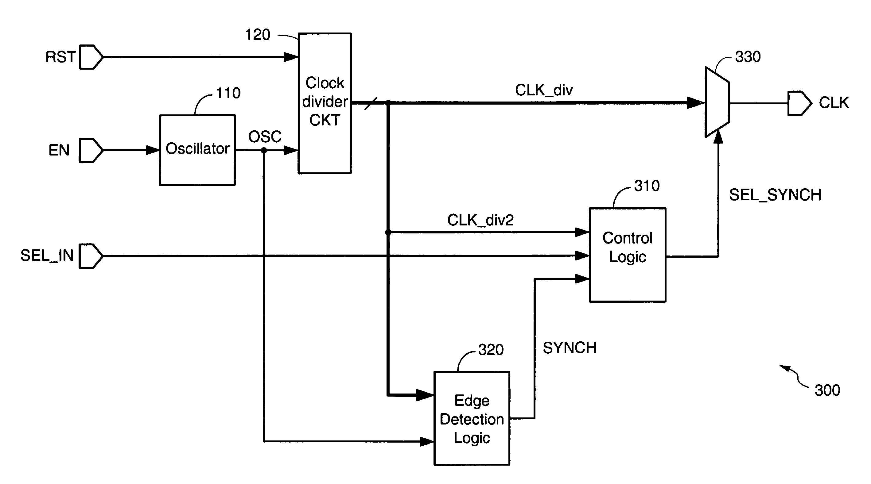
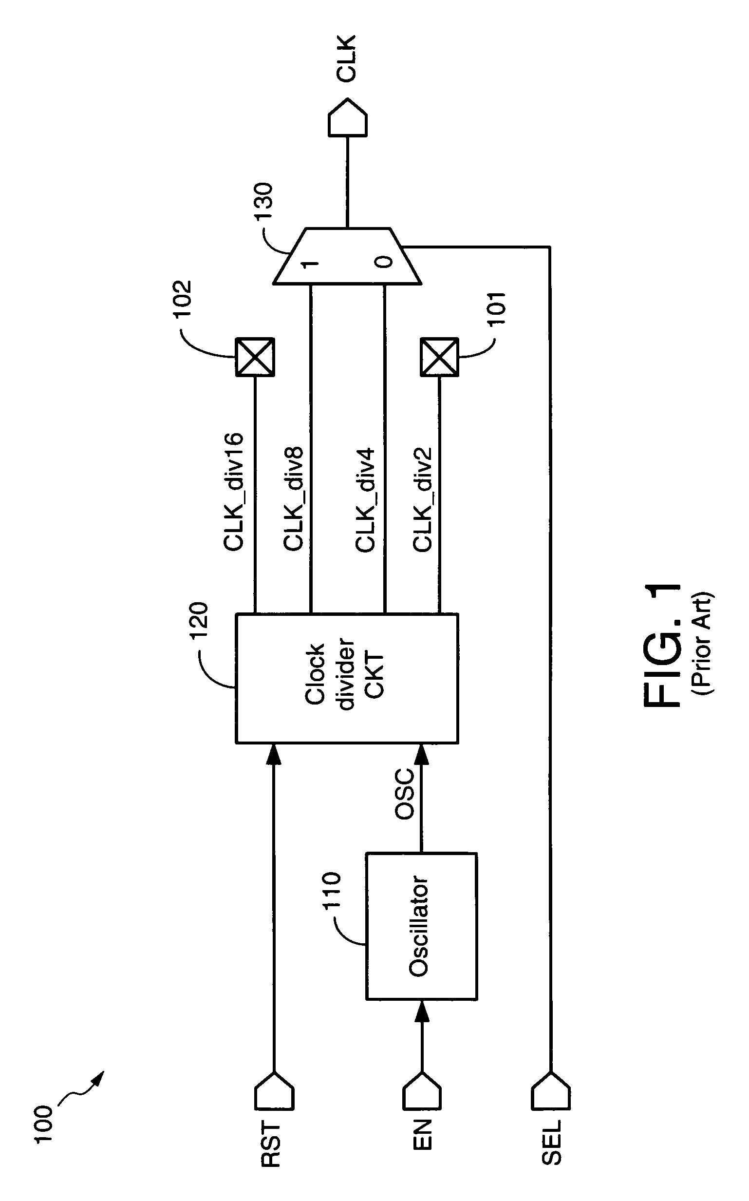
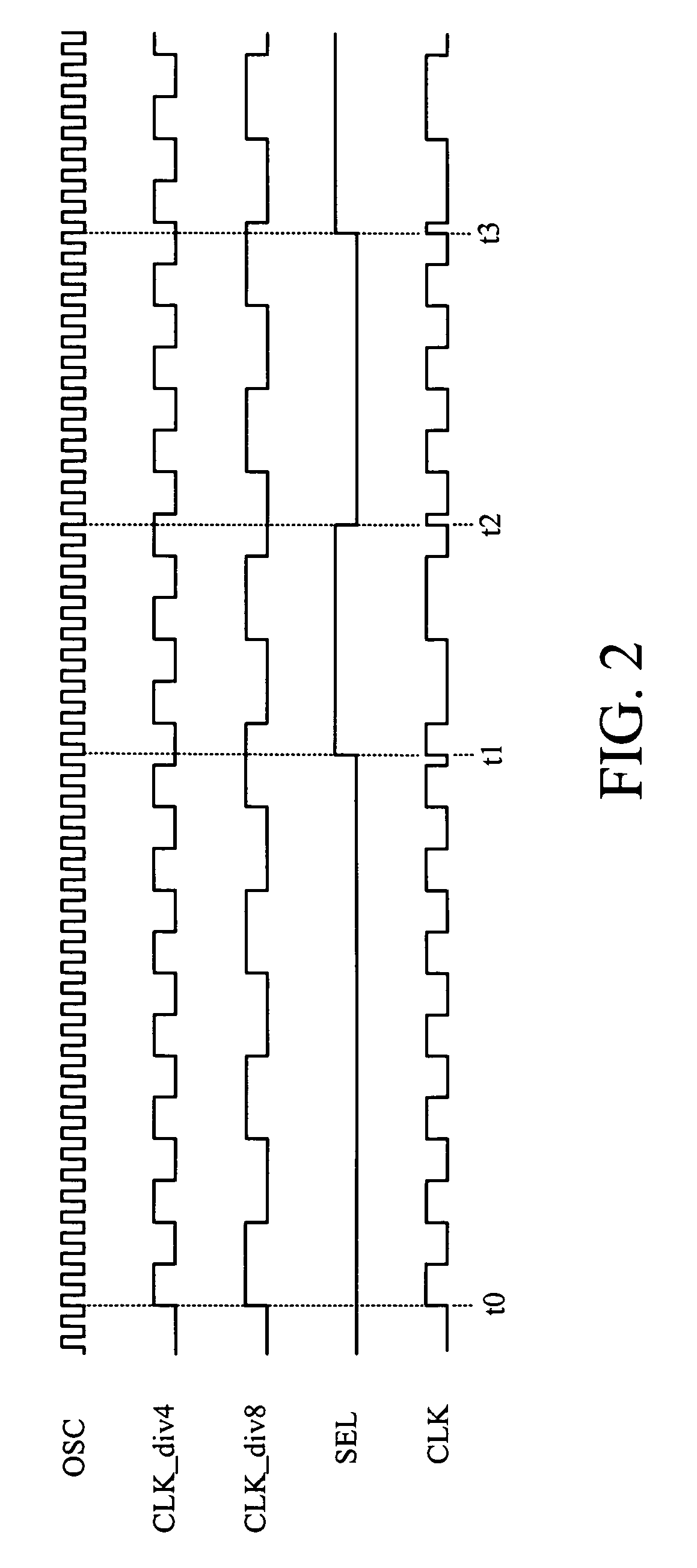
[0022]The present invention is applicable to a variety of integrated circuits and systems, and is particularly useful for devices that require glitchless switching among different input clock signals without halting the output clock signal. Embodiments of the present invention are described below in the context of a clock divider circuit that generates four different clock signals in response to an oscillation signal for simplicity only. It is to be understood that embodiments of the present invention may be used to switch among any number of different clock signals generated in any suitable manner. In the following description, for purposes of explanation, specific nomenclature is set forth to provide a thorough understanding of the present invention. In other instances, well-known circuits and devices are shown in block diagram form to avoid obscuring the present invention. Further, the logic levels assigned to various signals in the description below are arbitrary, and thus can b...


PUM


Abstract

A clock selection circuit includes an output multiplexer, control logic, and edge detection logic. The multiplexer includes inputs to receive multiple input clock signals, an output to generate the output clock signal, and a control terminal to receive a synchronized clock select signal. The control logic includes a first input to receive a clock select signal, a second input to receive a first control clock signal, a third input to receive a synchronization signal, and an output to selectively update the synchronized clock select signal with transitions in the clock select signal. The edge detection logic includes first inputs to receive the multiple input clock signals, a second input to receive a second control clock signal, and an output to generate the synchronization signal.

Description

FIELD OF INVENTION[0001]The present invention relates generally to clock signals in integrated circuit (IC) devices, and more specifically to switching an output clock signal among multiple input clock signals in IC devices.DESCRIPTION OF RELATED ART[0002]It is desirable for an IC device to be able to operate using clock signals having different frequencies, for example, so that the device can communicate with other devices that utilize various different clock frequencies and to allow the device to use the fastest possible clock signal. Thus, many IC devices include a clock selection circuit that can switch the operating clock signal among multiple input clock signals that have different frequencies.[0003]FIG. 1 shows a prior art clock selection circuit 100 that includes an oscillator 110, a clock divider circuit 120, and a multiplexer (MUX) 130. Oscillator 110 can be any well-known oscillator (e.g., such as a ring oscillator) or circuit that generates an oscillating output signal O...

Claims


Application Information

Patent Timeline
Patent Type & Authority Patents(United States)
IPC IPC(8): G06F1/08
CPCG06F1/08
Inventor NGUYEN, ANDY T.ZHOU, SHI-DONG
Owner XILINX INC
Why Eureka
Try Eureka