Solid freeform fabrication system and method

a freeform and fabrication system technology, applied in the field of solid material fabrication, can solve the problems of reducing the density of the microstructure of the material, affecting the quality of the part,

Active Publication Date: 2006-07-11
HENN DAVID S
View PDF5 Cites 143 Cited by
  • Summary
  • Abstract
  • Description
  • Claims
  • Application Information

AI Technical Summary

Problems solved by technology

As compared to other part fabrication techniques casting typically yields weaker parts due to the affects of cooling, which causes the material microstructure to be less dense.
Pores and voids within the part are also problematic to this process since the process can introduce pockets of gas bubbles into the casting.
Castings are also limited by the choices of materials that may be cast due to cooling rate issues.
This allows much more complex or unitized parts to be built, however, cost increases as compared to reusable molds because the mold must be recreated for each part produced.
Modern forges can produce a great deal of force.
Part overhang areas, closed regions, and complex vertical surfaces cannot be fabricated using the forging process.
Although there have been advances in controlling the temperature of the stock material and advances in using shaped tools, tremendous amounts of energy are required to bring a large billet to temperature before a forging tool can shape it.
A forging operation generally requires a large capital investment and long lead times for tool fabrication.
Additionally, creating custom tools for closed die forging is expensive and once the tool is fabricated, it cannot be changed without considerable expense and delay.
Machining operations are time consuming and material consumption inefficient.
This has improved the cost of machined parts, but the capital investment in purchasing new machines has kept supplier competition down and prices high.
Issues with gouging and cutter longevity are problematic and are still being addressed in the industry.
These are labor-intensive approaches that add weight and complexity due to redundant structure and fasteners.
Prior art additive systems are limited in deposition rates to about 15 cm3 per hour.
While these systems yield good results for small parts, the inefficient power consumption of laser power sources and low deposition rates make them impractical of larger part fabrication projects.
Additive manufacturing has increased flexibility in part production, however, size is limited and finish machining operation carry many of the same limits as machined parts.
Exotic alloys are frequently employed, which are expensive as raw material and are difficult to machine.
Corrosive Material Handling

Method used


Image

  • Solid freeform fabrication system and method
  • Solid freeform fabrication system and method
  • Solid freeform fabrication system and method

Examples


Embodiment Construction

[0069]Illustrative embodiments and exemplary applications will now be described with reference to the accompanying drawings to disclose the advantageous teachings of the present invention.

[0070]While the present invention is described herein with reference to illustrative embodiments for particular applications, it should be understood that the invention is not limited thereto. Those having ordinary skill in the art and access to the teachings provided herein will recognize additional modifications, applications, and embodiments within the scope thereof and additional fields in which the present invention would be of significant utility.

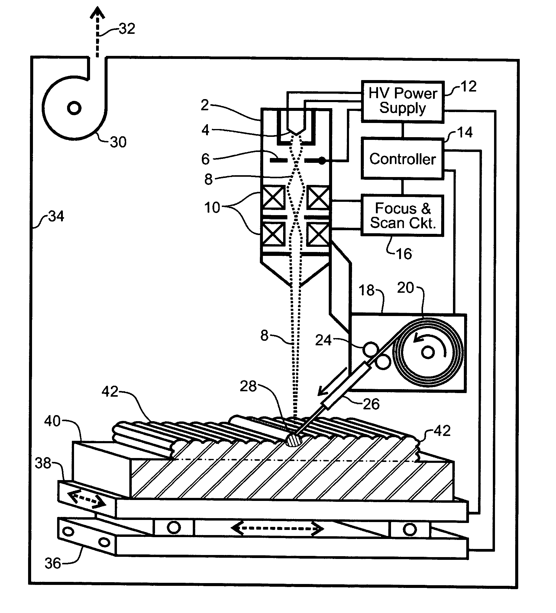
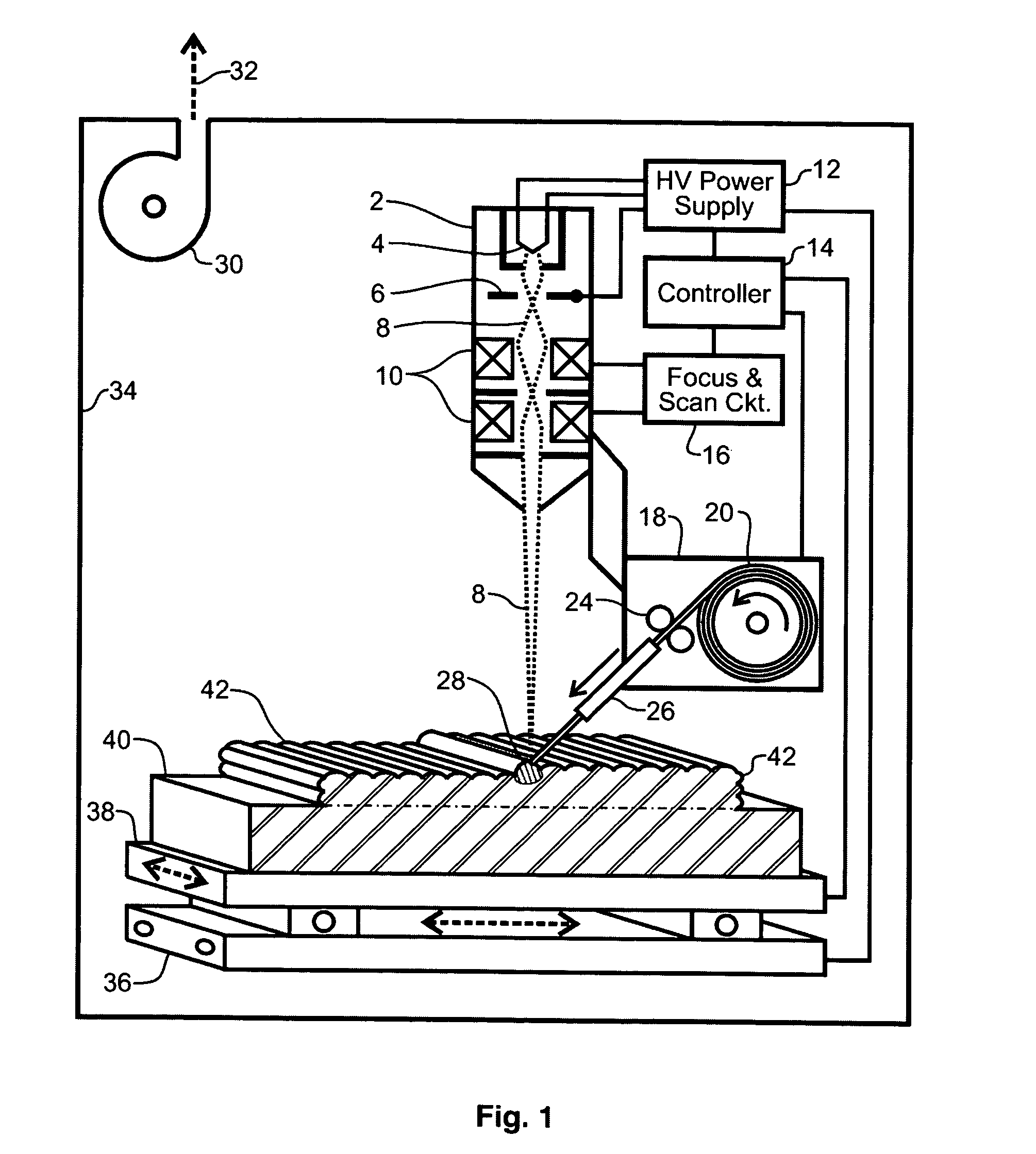
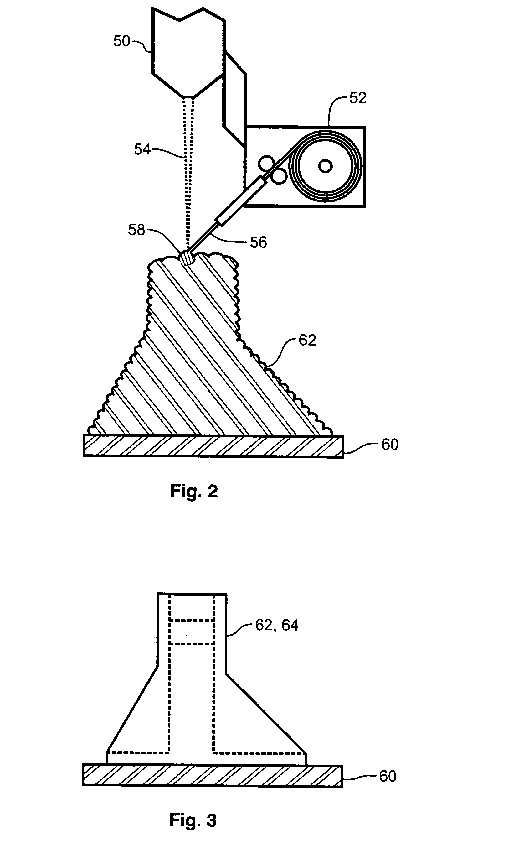
[0071]The present invention teaches a revolutionary advancement in the state of the art for solid freeform fabrication. An illustrative embodiment of the present invention system and method uses an electron beam as the heat source and wire as the feedstock material in the production of large, complex shape, metal parts conforming to a mold or layered...


PUM

PropertyMeasurementUnit
net weightaaaaaaaaaa
geometric volumeaaaaaaaaaa

Abstract

A system and method of solid freeform work piece fabrication through layered deposition of feedstock material on a mold structure. An energy beam and feedstock are fed to a feed point adjacent to a mold structure, thereby forming a molten puddle. The feed point is moved relative to the mold structure, thereby advancing the molten puddle of presently fed feedstock and rapidly solidifying previously fed feedstock. The feed point is sequentially advanced within a predetermined geometric volume containing at least a portion of the mold structure, thereby sequentially fusing the feedstock, by action of the advancing molten puddle, into a near net shape work piece built-up upon the mold structure.

Description

BACKGROUND OF THE INVENTION[0001]1. Field of the Invention[0002]The present invention relates to solid material fabrication. More specifically, the present invention relates to solid freeform fabrication through feedstock deposition using an energy beam and advancing a molten puddle of rapidly solidifying material layered upon a mold or base structure.[0003]2. Description of the Related Art[0004]Metal and composite part fabrication and utilization permeates modern industry. An enormous range of products incorporate such parts, which may range in size from tiny components to major structural elements of huge machines. Industry has developed a wide range of fabrication techniques for such parts, which address materials, costs, development time, and economies of production. Among these fabrication techniques are casting, forging, machining, stamping, assemblies, and additive manufacturing.[0005]The casting process essentially consists of making a shaped mold, and then pouring or inject...

Claims


Application Information

Patent Timeline
Patent Type & Authority Patents(United States)
IPC IPC(8): B22D23/00
CPCB22F3/003B22F3/008B22F3/1055G03F7/0037B82Y30/00B22F2003/1056B22F2003/1058B33Y10/00B33Y30/00Y02P10/25B22F10/40B22F12/38B22F12/41B22F10/25B22F12/37B23K15/0086B23K26/342
Inventor HENN, DAVID S.
Owner HENN DAVID S
Why Eureka
Try Eureka