Casing assembly for the turbine of an exhaust turbochanger

a technology of turbine casing and turbocharger, which is applied in the direction of machines/engines, stators, liquid fuel engines, etc., can solve the problems of unreasonably high unreasonably large weight and space demands, and accept only small heat energy, so as to reduce weight, reduce wall thickness, and facilitate manufacture of insulation

Inactive Publication Date: 2006-07-11
BORGWARNER INC
View PDF2 Cites 46 Cited by
  • Summary
  • Abstract
  • Description
  • Claims
  • Application Information

AI Technical Summary

Benefits of technology

[0011]The insulation also keeps the outer shell of the affected components relatively cool. This is an important advantage, since the turbocharger can be thus be arranged along with other heat sensitive components, for example with heat sensitive cables. The re-radiation towards the body is also minimized so that the exterior paint remains unharmed. It is understood that the low wall thickness of the sheet metal wall also contributes to the decreased weight.
[0012]It is especially convenient to manufacture the insulation from a sheet covering around the sheet metal wall. In doing so, an air gap should remain between the sheet metal wall and the sheet covering, creating an especially good insulation. The sheet covering can be substantially thinner than the sheet metal wall. Yet it provides an excellent heat barrier, since passage from one medium to another—here air to the sheet covering—creates a heat transfer barrier.
[0013]The sheet covering also fulfills a further function: It increases the rigidity of the entire design. This can lead to further minimizing the sheet metal wall which is contacted by the gas flow.

Problems solved by technology

That is, lowering pollutant emissions during the cold start phase leaves much to be desired, and weight and space demands are unreasonably high.
This means that it accepts only little heat energy from the exhaust, and therefore only removes little heat from the exhaust during the cold start phase.

Method used


Image

  • Casing assembly for the turbine of an exhaust turbochanger
  • Casing assembly for the turbine of an exhaust turbochanger
  • Casing assembly for the turbine of an exhaust turbochanger

Examples


Embodiment Construction

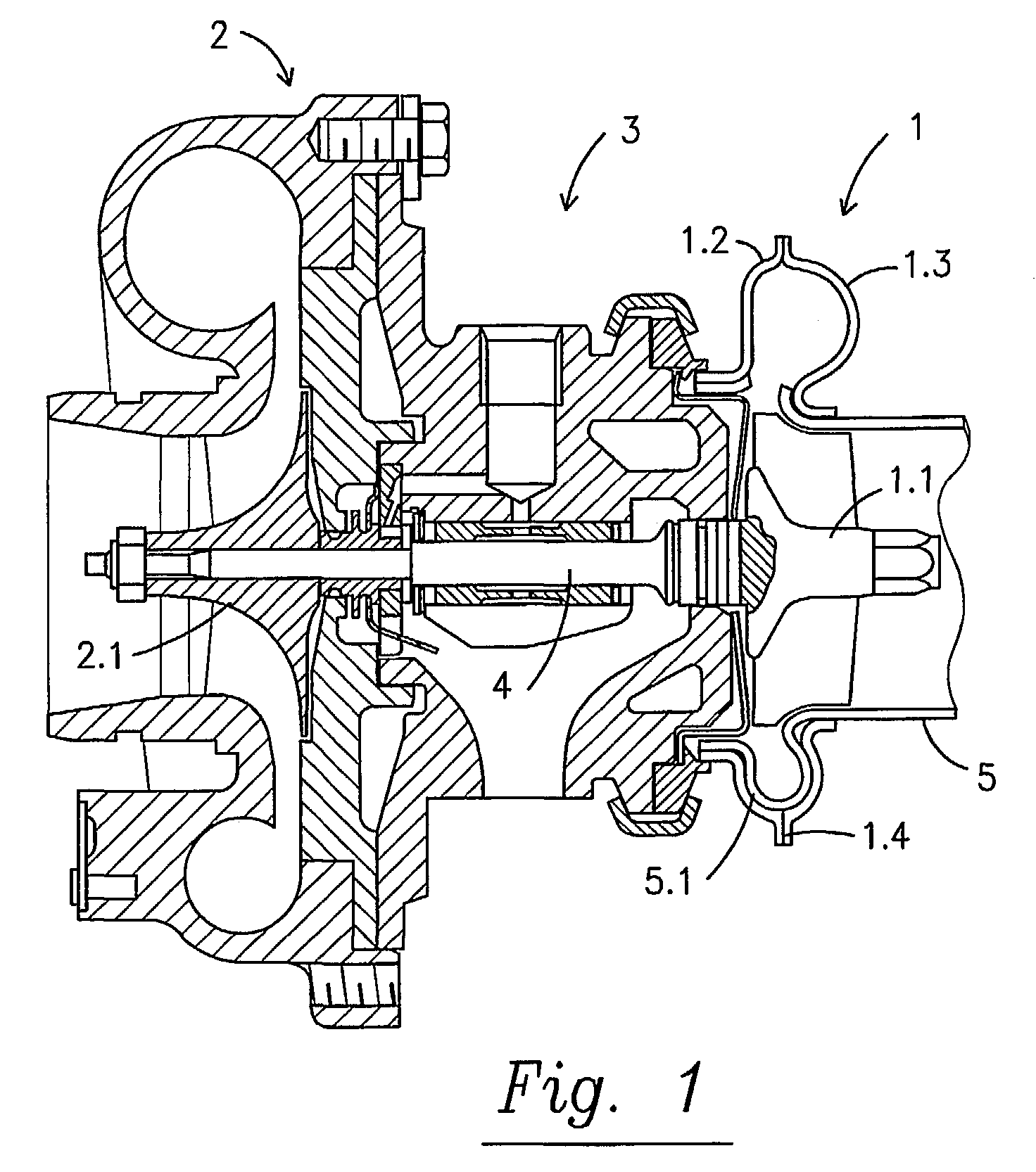
[0023]The exhaust turbocharger shown in FIG. I includes a turbine I as the most important component, a compressor 2 as well as a bearing 3. The turbine I has turbine wheel 1. 1 and the compressor has a compressor wheel 2. 1. Both wheels are set on a common shaft 4. The shaft 4 is supported by bearing 3.

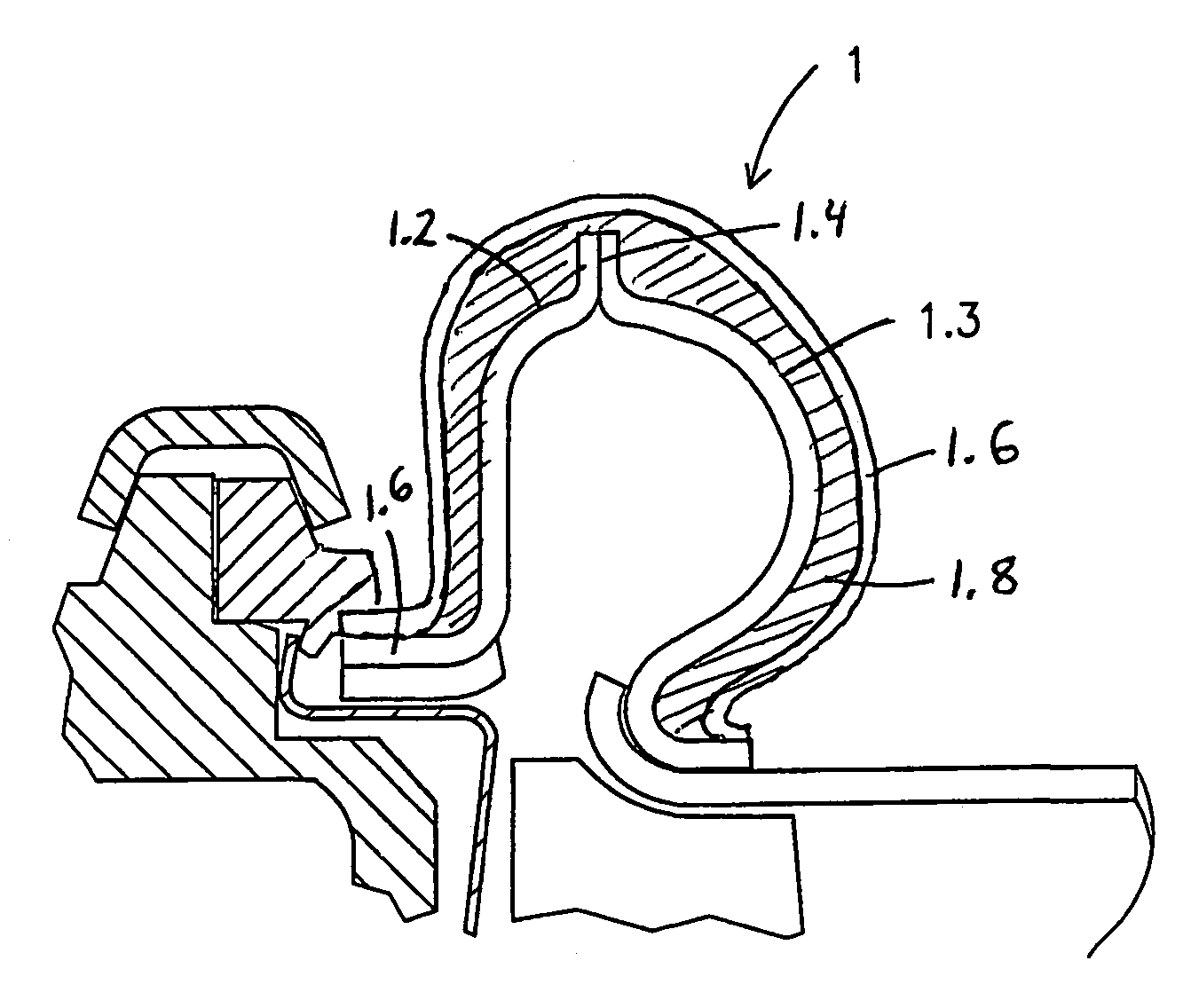
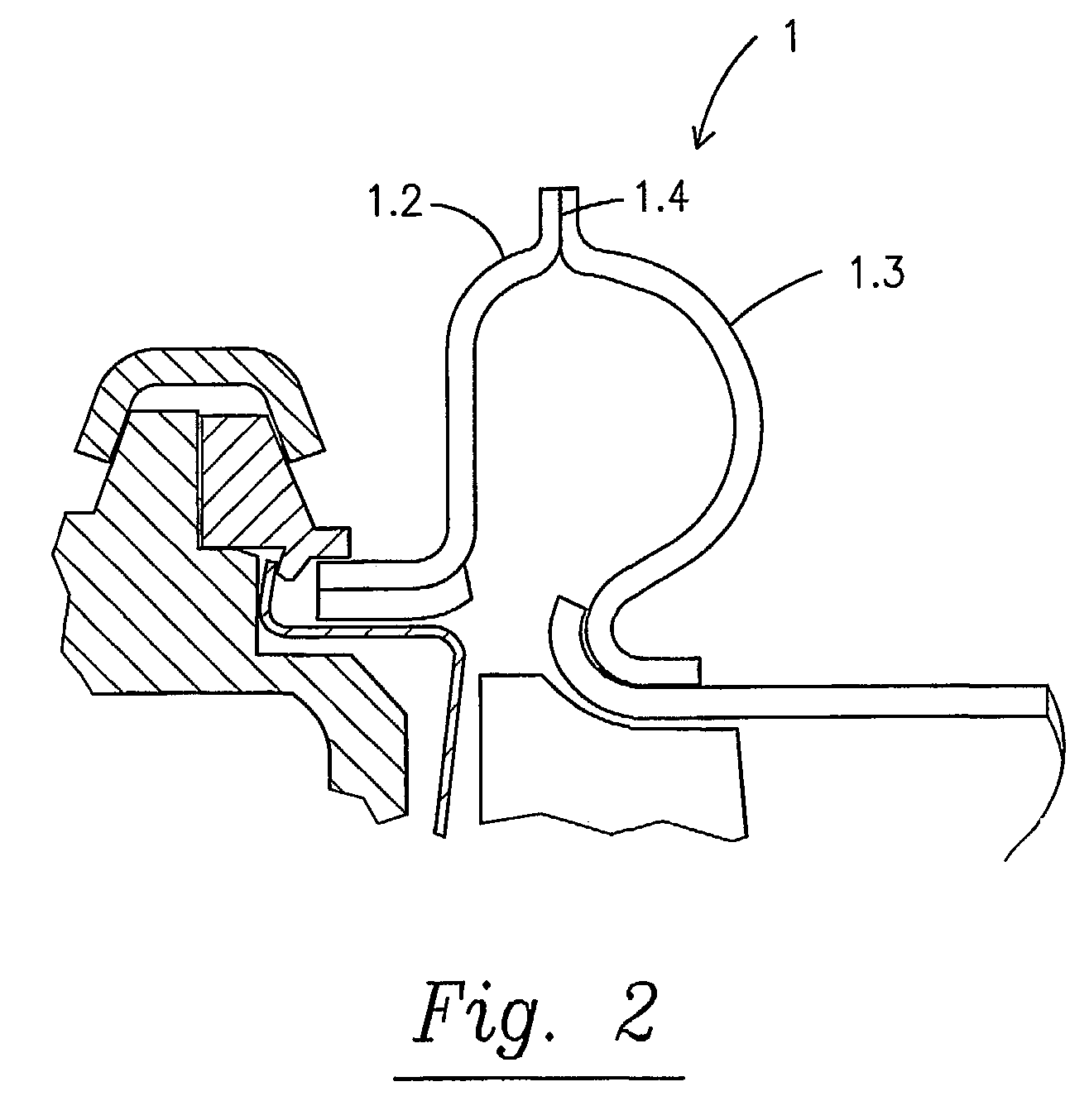
[0024]The essential feature of the illustrated view is the turbine casing 1. In the present case, it is manufactured from sheet steel. It is usually a spiral casing. It is built from two main parts, namely from an inner component 1.2 and an outer component 1.3. The separation joint 1.4 between these two 3 parts runs along the apex line of the spiral casing 1. There, a welded seam is made.

[0025]The wall thickness of both casing parts amount to 1.0 mm. The sheet metal is highly heat resistant (T3>than 1000° C.).

[0026]The sheet metal wall is surrounded by an insulation 1.8 as shown in FIG. 7 which is located on the outer skin of the sheet metal, and due to its heat insulating properties,...


PUM


Abstract

A spiral casing for a turbine of a turbocharger is made from thin (0,2 to 2 mm thick) sheet metal. The spiral casing can be made from two matching parts and can be insulated.

Description

CROSS REFERENCE TO RELATED APPLICATIONS[0001]This application is a national stage of PCT / US01 / 18273 filed Jun. 6, 2001 and based upon DE 100 28 160.5 filed Jun. 7, 2000 under the International Convention.BACKGROUND OF THE INVENTION[0002]1. Field of the Invention[0003]The invention concerns a casing assembly for the turbine of an exhaust turbocharger. The invention especially concerns the spiral casing of the turbine.[0004]2. Discussion of the Related Art[0005]Exhaust turbochargers are a must in modern vehicles. The most important components include a turbine and a compressor. These two components are located on one and the same shaft. The exhaust of the internal combustion engine is conducted to the turbine. The exhaust powers the turbine. Then the turbine in turn powers the compressor. This takes in air from the environment and compresses it. The compressed air is then used for combustion in the engine. The purpose of exhaust turbochargers is to minimize the exhaust emissions as we...

Claims


Application Information

Patent Timeline
Patent Type & Authority Patents(United States)
IPC IPC(8): F01D25/08F01D9/02F01D25/14
CPCF01D9/026F01D25/145F05D2220/40
Inventor ALLMANG, RUEDIGERCLAUS, HARTMUTSIMON, VOLKER
Owner BORGWARNER INC
Why Eureka
Try Eureka