

Medical device balloon
a medical device and balloon technology, applied in the field of balloon catheters, can solve the problems of low flexibility and softness of non-compliant balloons, trauma to the vessel wall, and difficulty in providing low-compliant balloons with high flexibility and softness for enhanced trackability, and achieves lower than expected compliance and enhanced softness and flexibility
- Summary
- Abstract
- Description
- Claims
- Application Information
AI Technical Summary
Benefits of technology
Problems solved by technology
Method used
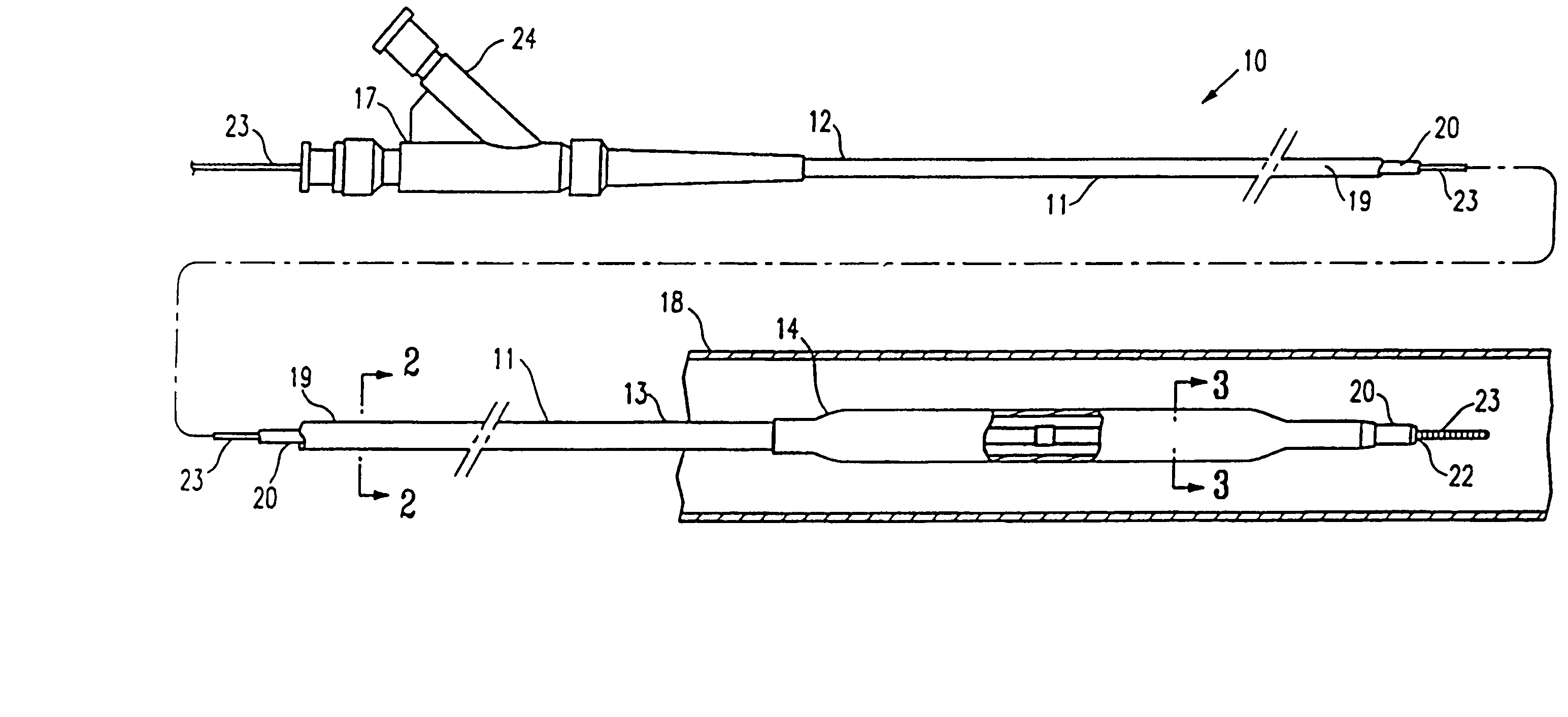
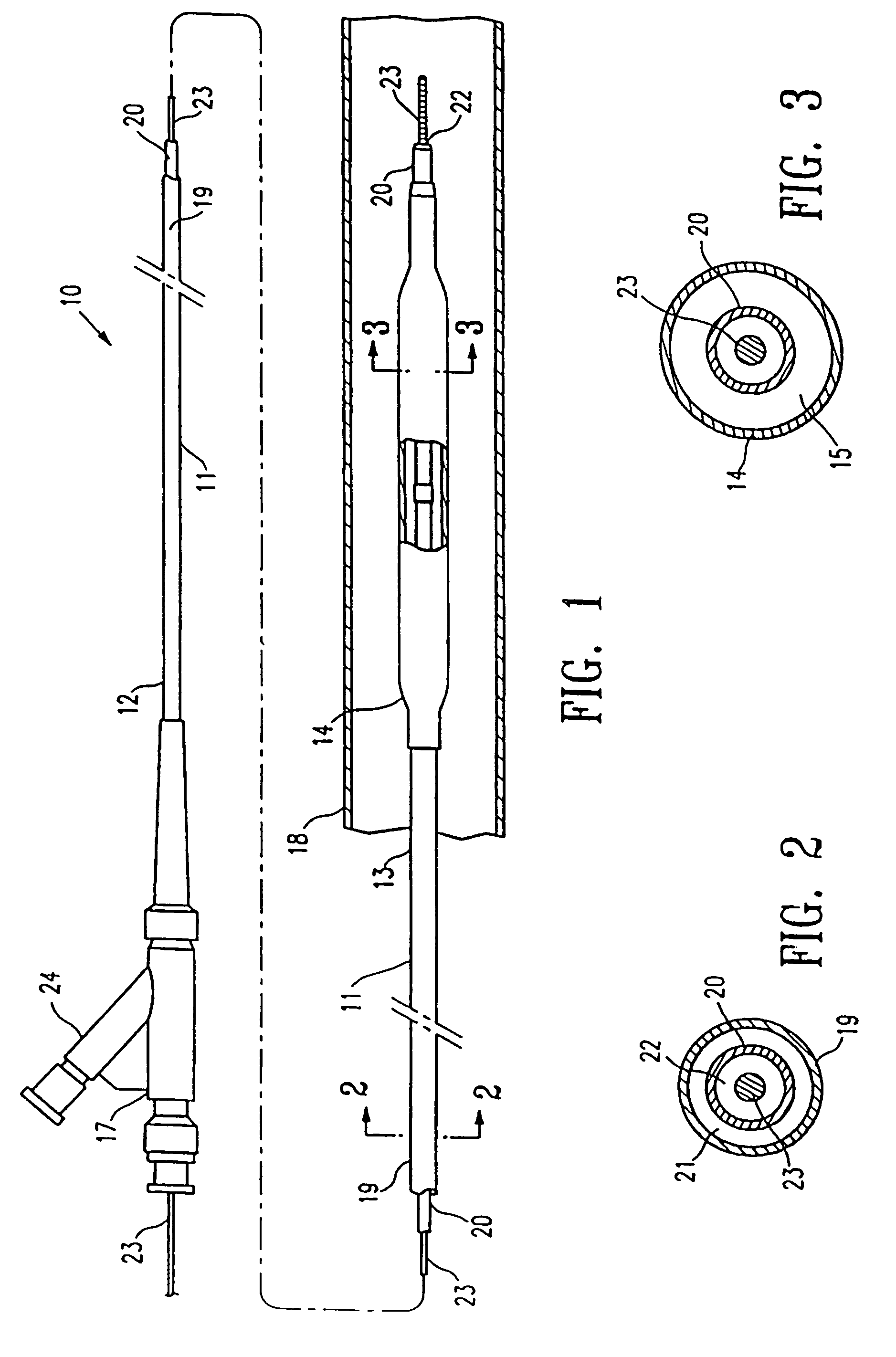
Image

Examples
example 1
[0027]Polymeric blends were formed using PEBAX 7033 SA01 and PEBAX 6333 SA01. PEBAX 7033 (hereafter “PEBAX 70D”) has a Shore durometer hardness of about 70D, a flexural modulus of 67,000 psi, and tensile strength of 8300 psi. PEBAX 6333 (hereafter PEBAX 63D) has a Shore durometer hardness of about 63D, a flexural modulus of 49,000 psi, and a tensile strength of 8100 psi. PEBAX 70D was blended with PEBAX 63D, where the PEBAX 70D was 40% by weight of the total blend and the PEBAX 63D was 60% by weight of the total blend. The blend was used to prepare 15 samples of balloon tubing having a mean ID of about 0.018 inch (0.46 mm) and a mean OD of about 0.034 inch (0.86 mm), with a blow up ratio of 6.6. The balloon tubing may be necked in a die before expanding the balloon tubing in a mold to form the balloon. A balloon was formed from the balloon tubing by axially stretching the balloon tubing at elevated temperature, and expanding the balloon tubing in a balloon mold while heating the bal...
example 2
[0029]PEBAX 70D was blended with PEBAX 63D, where the PEBAX 70D was 40% by weight of the total blend and the PEBAX 63D was 60% by weight of the total blend. The blend was used to prepare balloon tubing having an ID of about 0.0195 inch (0.495 mm) and an OD of about 0.0355 inch (0.902 mm), which was used to prepare balloons having a single wall thickness of about 0.00065 (0.017 mm) to about 0.0008 inch (0.02 mm), with a blow up ratio of about 6.0, using a procedure similar to the procedure outlined in Example 1, except that the same heated air nozzel that was used to heat the balloon tubing during the expansion of the balloon tubing in the mold was used to heat treat the entire length of the balloon within the mold after the balloon tubing is expanded in the mold. Similarly, a second balloon was formed from 100% PEBAX 70D.
[0030]Radial (OD) compliance and rupture pressure measurement were made on blown balloons, as listed below in Table 2. The compliance was measured from 8 atm (nomin...
example 3
[0032]A first balloon was formed from a blend of 60 weight % PEBAX 70D and 40 weight % PEBAX 63D. The blend was used to prepare balloon tubing having an ID of about 0.019 inch (0.495 mm) and an OD of about 0.0355 inch (0.902 mm), and a balloon was formed from the balloon tubing by axially stretching and expanding the balloon tubing in a first mold at 370 psi and 235° C. (temperature controller set temperature) to an OD of 2.0 mm, cooling the balloon in the mold at the elevated pressure, expanding the balloon in a second mold at 370 psi and 237° C. (temperature controller set temperature) to an OD of 3.0 mm and a length of 20 mm, and cooling the balloon in the mold at the elevated pressure. Similarly, a second balloon was formed from a blend of 80 weight % PEBAX 70D and 20 weight % PEBAX 63D, and a third balloon was formed from 100% PEBAX 63D.
[0033]Radial (OD) compliance and rupture pressure measurement were made on blown balloons, as listed below in Table 3. The compliance was measu...
PUM
| Property | Measurement | Unit |
|---|---|---|
| Fraction | aaaaa | aaaaa |
| Fraction | aaaaa | aaaaa |
| Fraction | aaaaa | aaaaa |
Abstract
Description
Claims
Application Information